| Tweet |

Custom Search
|
|
 
|
||
|
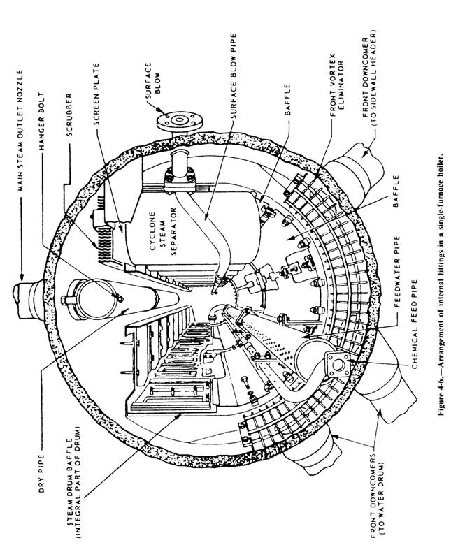
INTERNAL FITTINGS Components of the steam drum area are known as INTERNAL FITTINGS. The internal fittings we will discuss are the feedwater distribution, the chemical injection, and the steam and water separator. This equipment is used to direct the flow of steam and water within the steam drum and the desuperheaters, which are located either in the steam drum or the water drum. We will also discuss the economize in this section. This component is not considered an internal fitting, but its role is important to the function of the steam drum. The design and arrangement of a steam drum's internal fittings will vary somewhat from
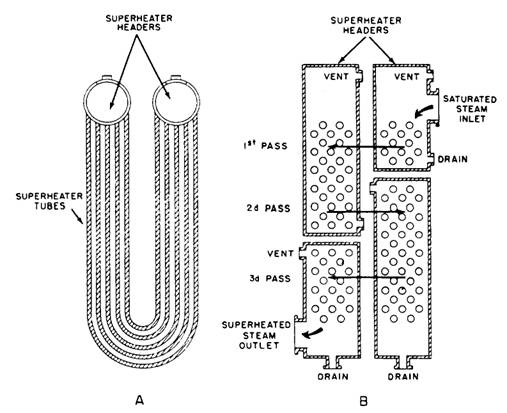
Figure 4-7.-Diagram of a superheater. one type of boiler to another and from one boiler manufacturer to another. Figure 4-6 shows the arrangement of the steam drum internal fittings in a single-furnace boiler. The feedwater pipe receives feedwater from the economizer and distributes it throughout the length of the steam drum. The chemical feed pipe is used to inject chemicals into the boiler to maintain the proper pH and phosphate balance in the boiler water. The surface blow pipe is used to remove suspended solid matter that floats on top of the water and to lower the steam drum water level, when necessary. The surface blow pipe is also used to blow water out to lower the chemical level in the boiler when it becomes too high. The dry pipe is used to direct the steam to the steam drum outlet nozzle after it leaves the scrubbers. The vortex eliminators are used to reduce the swirling motion of the water as it enters the downcomers. The baffle plates are used to direct the steam to the steam separators. The cyclone steam separators remove moisture from the steam. This is accomplished by the steam spinning or changing direction. The water drains back into the steam drum while the steam continues upward through a screen and scrubber that removes still more moisture. After the steam leaves the scrubbers, it goes to the dry pipe fig 4-6. From there it leaves the steam drum through the steam drum outlet. Figure 4-7- view A, shows the steam going to the inlet header of the superheater and passing through the U-shaped tubes of the superheater to the next header fig 4-7 view B). This header is called the first pass or intermediate header. Steam may pass through the U-shaped tubes several times before passing to the outlet header. Each time the steam goes from one header to the next header it is called a pass. The number of passes the steam makes in a superheater varies with different boilers and the degree of superheat that is required for a particular ship.
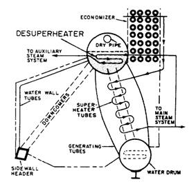
Figure 4-8.-Vertical superheater. As the steam passes through the superheater tubes, it is heated by the hot gases from combustion, which flow around the tubes. In some boilers, the superheater headers are installed parallel with the water drum; and the tubes are installed vertically fig 4-8. These are called vertical superheaters. Another boiler internal fitting is the desuperheater. It maybe located either in the steam drum or in the water drum. All the steam generated in a single-furnace boiler is led through the superheater. However, since some auxiliary machinery is not designed for superheated steam, the steam must be cooled down. This is done with a desuperheater. The desuperheater gets steam from the superheater outlet, as shown in figure 4-9 The desuperheater is submerged in water either in the steam drum or in the water drum. As the steam passes through the desuperheater, it is cooled for use in the auxiliary steam systems.
Figure 4-9.-Relative position of desuperheater tubes.
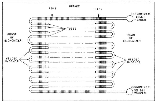
Figure 4-10.-Side view of an economizer. It is important that all internal fittings are properly installed and in good working condition. If excessive moisture is carried over into the superheater, serious damage will result in the superheater tubes, piping, and turbines. The economizer figure 4-10 is an arrangement of tubes installed in the uptake space from the furnace. The economizer tubes have metal projections from the outer tube surfaces. These projections are called by various names, including FINS, STUDS, RINGS, or GILL RINGS. They are made of aluminum, steel, or other metals, in a variety of shapes. These projections serve to extend the heat transfer surface of the tubes on which they are installed. Before entering the steam drum, all feedwater flows through the economizer tubes. The economizer tubes are heated by the rising gases of combustion. The feedwater is warmed or preheated by the combustion gases that would otherwise be wasted as they pass up the stack. In figure 4-11 you can see that the economizer is positioned on top of the boiler. There it acts as a preheater. So far, you have learned how the water gets to the boiler and what happens while it's there. Next, let's find out how the water is heated, where the heat comes from, and what boiler components are necessary for generating this heat. |
||
|
||