| Tweet |

Custom Search
|
|
 
|
||
|
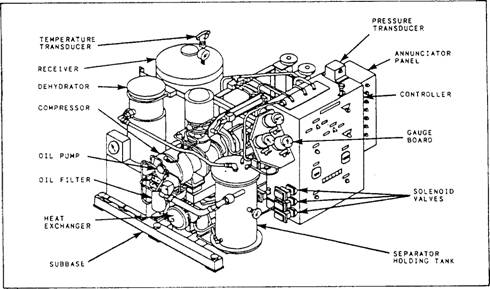
CLASSIFICATION OF AIR COMPRESSORS An air compressor may be classified according to pressure (low, medium, or high), type of compressing element, and whether the discharged air is oil free. Because of our increasing need for oil-free air aboard ship, the oil-free air compressor is gradually replacing most of the standard low-pressure and high-pressure air compressors. For this reason, most of this discussion is focused on the features of oil-free air compressors. The Naval Ships' Technical Manual (NSTM), chapter 551, lists compressors in three classifications: 1. Low-pressure air compressors (LPACs), which have a discharge pressure of 150 psi or less 2. Medium-pressure compressors, which have a discharge pressure of 151 psi to 1,000 psi 3. High-pressure air compressors (HPACs), which have a discharge pressure above 1,000 psi Low-Pressure or Ship's Service Air Compressors The two types of LPAAs that are used on naval ships are the screw type and the reciprocating type. SCREW TYPE.- The helical-screw type of compressor is a relatively new design of oil-free air compressor. This low-pressure air compressor is a single-stage, positive-displacement, axial-flow, helical-screw type of compressor. It is often referred to as a screw-type compressor. Figure 10-23 shows the general arrangement of the LPAC unit. In the screw-type LPAC, compression is caused by the meshing of two helical rotors (a male and a female rotor, as shown in fig 10-24) located on parallel shafts and enclosed in a casing. Air inlet and outlet ports are located on opposite sides of the casing. Atmospheric air is drawn into the compressor through the filter-silencer. The air passes through the air cylinder-operated unloader (butterfly) valve and into the
Figure 10-23.-LPAC unit (screw type.)
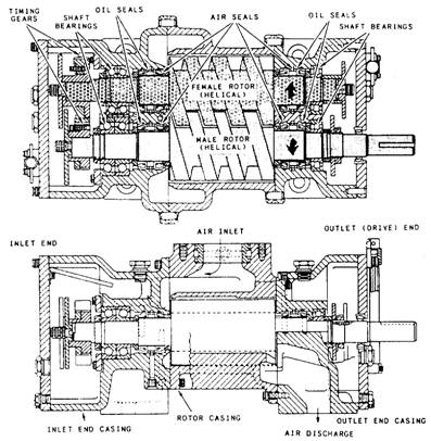
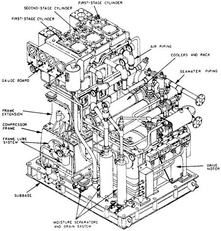
Figure 10-24: LPAC, compressor section. inlet part of the compressor when the valve is in the open (load) position. Fresh water is injected into the airstream as it passes through the inlet port of the compressor casing. The injected fresh water serves two purposes: 1. It reduces the air discharge temperature caused by compression. 2. It seals the running clearances to minimize air leak. Most of the injected water is entrained into the airstream as it moves through the compressor. The compression cycle starts as the rotors unmesh at the inlet port. As rotation continues, air is drawn into the cavity between the male rotor lobes and into the grooves of the female rotor. The air is trapped in these grooves, or pockets, and follows the rotative direction of each rotor. As soon as the inlet port is closed, the compression cycle begins as the air is directed to the opposite (discharge) end of the compressor. The rotors mesh, and the normal free volume is reduced. The reduction in volume (compression) continues with a resulting increase in pressure, until the closing pocket reaches the discharge port. The entrained water is removed from the discharged air by a combined separator and water holding tank. The water in the tank passes through a seawater-cooled heat exchanger. The cooled water then recirculates to the compressor for reinfection. During rotation and throughout the meshing cycle, the timing gears maintain the correct clearances between the rotors. Since no contact occurs between the rotor lobes and grooves, between the rotor lobes and casing, or between the rotor faces and end walls, no internal oil lubrication is required. This design allows the compressor to discharge oil-free air. For gear and bearing lubrication, lube oil from a force-feed system is supplied to each end of the compressor. Mechanical seals serve to keep the oil isolated from the compression chamber. RECIPROCATING TYPE.- All reciprocating air compressors are similar to each other in design and operation. The following discussion describes the basic components and principles of operation of a low-pressure reciprocating air compressor. The LPAC is a vertical, two-stage single-acting compressor that is belt-driven by an electrical motor. Two first-stage cylinders and one second-stage cylinder are arranged in-line in individual blocks mounted to the crankcase (frame) with a distance piece (frame extension). The crankcase is mounted on a subbase that supports the motor, moisture separators, and a rack assembly. The intercooler, aftercooler, freshwater heat exchanger, and freshwater pump are mounted on the rack assembly. The subbase serves as the oil sump. Figure 10-25 shows the general arrangement of the reciprocating-type compressor.
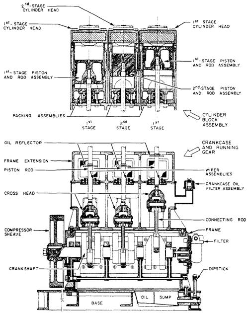
Figure 10-25.-LPAC (reciprocating type). The compressor is of the crosshead design. Figure 10-26 shows shows cross-sectional views of the LPAC. The frame extension houses the crossheads and crosshead guides and is open to the atmosphere. It separates the cylinders, which are not oil lubricated, from the crankcase. Oil wiper assemblies (seals) are located in the frame extension to scrape lubricating oil off the piston rods when the compressor is in operation. Oil deflector plates are attached to the piston rods to prevent any oil that creeps through the scrapers from entering the cylinders. Oil that is scraped from the piston rods drains back to the sump. Air leak along the piston rods is prevented by full floating packing assemblies bolted to the underside of the cylinder blocks. During operation, ambient air is drawn into the first-stage cylinders through the inlet filter silencers and inlet valves during the downstroke. When the piston reaches the bottom of its stroke, the inlet valve closes and traps the air in the cylinder. When the piston moves upward, the trapped air is compressed and forced out of the first-stage cylinders, through the first-stage cooler and the first-stage moisture separator. When the second-stage piston starts its downstroke, the air is drawn into the second-stage cylinder. Then, it is further
Figure 10-26.-LPAC, cross-sectional views (reciprocating type.) compressed, followed by a cooling and moisture removal process similar to the first stage. High-Pressure Air Compressors The HPAC is a vertical, five-stage, reciprocating air compressor. It is driven by being directly connected to an electrical motor. Refer t0 figures 10-27 and 10-28 as we describe the compressor. The subbase supports the compressor assembly, the electric drive motor, and the coolers and rack assembly. The crankcase is bolted directly to the subbase and is made up of the frame and frame extension. The frame houses the crankshaft and oil pump. The frame extension is open to the atmosphere and isolates the conventionally lubricated frame from the oil-free cylinders. The crosshead guides are machined in the frame extension. A uniblock casting contains the first three-stage cylinders and is mounted on the frame extension i- . The cylinders are arranged in line. The first stage is in the center, the second stage is at the motor end, and the third stage is outboard. The fourth stage is mounted above the second stage, and the fifth stage is above the third stage. The fourth- and fifth-stage pistons are tandem mounted to the secondand third-stage pistons, respectively. During operation, ambient air is drawn into the first-stage cylinder through the inlet falter and inlet valves. The first stage is double acting, and air is drawn into the lower cylinder area as the piston is moving upward. At the same time, air in the upper cylinder is being compressed and forced out the upper discharge valve. As the piston moves downward, air is drawn into the upper cylinder; likewise, air in the lower cylinder is being compressed and forced out the lower discharge valve. Compressed air leaves the first-stage discharge valves and flows through the first-stage intercooler, and into the first-stage moisture separator. The first-stage separator has a small tank mounted on the side of the compressor frame below the gauge panel and a holding tank mounted below the cooler rack. The separators for the remaining stages handle smaller volumes of air due to compression; as a result, the separators and holding chambers are smaller and are integrated into one tank. Condensate is removed from the air as it collides with the internal tank baffles and collects in the holding chamber.
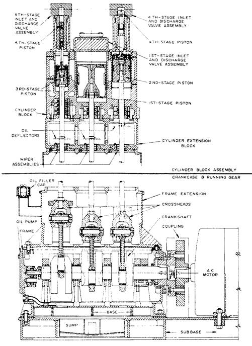
Figure 10-27.-HPAC.
Figure 10-28.-HPAC, cross-sectional views. Air from the first-stage separator is drawn into the single-acting, second-stage cylinder on tile upward stroke of the piston. As the piston travels downward, the air is compressed and forced out the discharge valve. The second-stage discharge air passes through the second-stage intercooler into the second separator. The third stage draws air from the second separator and compresses it in the same manner as in the second stage. Third-stage air enters a pulsation bottle before passing through the third-interstage cooler. Pulsation bottles are used after the third and fifth compression stages to minimize the shock effect of inlet and discharge pulses as well as pressure changes due to condensate draining. After passing through the third-interstage cooler and moisture separator, the air is drawn into the fourth-stage cylinder on the downstroke of the piston. As the piston travels upward, the air is compressed and forced out the discharge valve. Then it passes through the fourth-stage intercooler and moisture separator. Air is drawn into the fifth-stage cylinder on the piston downstroke and is compressed and discharged on the upstroke. The discharge air passes through the fifth-stage pulsation bottle, the aftercooler, the moisture separator, a back-pressure valve, and a check valve before entering the ships' HP piping. |
 |
|
|
||