| Tweet |

Custom Search
|
|
 
|
||
|
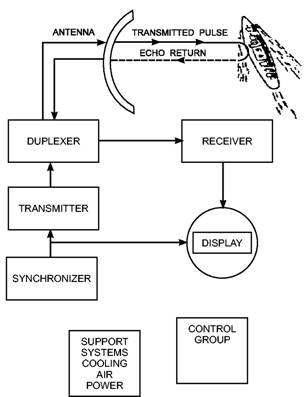
BASIC RADAR SYSTEMS Radar systems, like other complex electronics systems, are composed of several major subsystems and many individual circuits. Although modern radar systems are quite complicated, you can easily understand their operation by using a basic block diagram of a pulse-radar system. FUNDAMENTAL (PULSE) RADAR SYSTEM Since most radars used today are some variation of the pulse-radar system, this section discusses components used in a pulse radar. All other types of radars use some variation of these units. Refer to the block diagram in figure 1-4.
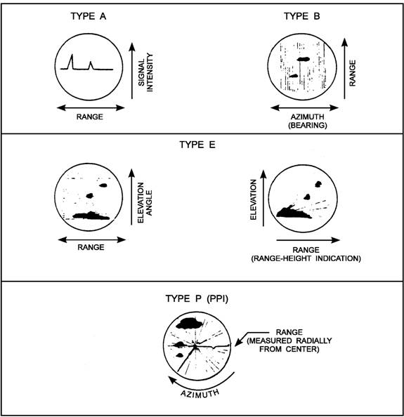
Figure 1-4.-Basic radar block diagram. Synchronizer The heart of the radar system is the ,synchronizer. It generates all the necessary timing pulses (triggers) that start the transmitter, indicator sweep circuits, and ranging circuits. The synchronizer may be classified as either self-synchronized or externally synchronized. In a self-synchronized system, pulses are generated within the transmitter. Externally synchronized system pulses are generated by some type of master oscillator external to the transmitter, such as a modulator or a thyratron. Transmitter The transmitter generates powerful pulses of electromagnetic energy at precise intervals. It creates the power required for each pulse by using a high-power microwave oscillator (such as a magnetron) or a microwave amplifier (such as a klystron) supplied by a low power RF source. For further information on the construction and operation of microwave components, review NEETS Module 11, Microwave Principles, NAVEDTRA 172-11-00-87. Duplexer The duplexer is basically an electronic switch that permits a radar system to use a single antenna to transmit and receive. The duplexer disconnects the antenna from the receiver and connects it to the transmitter for the duration of the transmitted pulse. The switching time is called receiver recovery time, and must be very fast if close-in targets are to be detected. Receiver The receiver accepts the weak RF echoes from the antenna system and routes amplified pulses to the display as discernible video signals. Because the radar frequencies are very high and difficult to amplify, a superheterodyne receiver is used to convert the echoes to a lower frequency, called the intermediate frequency (IF), which is easier to amplify. Displays Most of the radars that FCs operate and maintain have a display, or multiple displays, to provide the operator with information about the area the radar is searching or the target, or targets, being tracked. The usual display is a cathode-ray tube (CRT) that provides a combination of range, bearing (azimuth), and (in some cases) elevation data. Some displays provide raw data in the form of the signal from the radar receiver, while others provide processed information in the form of symbology and alphanumerics. Figure 1-5 shows four basic types of displays. There are other variations, but these are the major types encountered in fire control and 3-D search radars. TYPE A.-The type A sweep, or range sweep, display shows targets as pulses, with the distance from the left side of the trace representing range. Variations in target amplitude cause corresponding changes in the displayed pulse amplitude. The display may be bipolar video when used with Moving Target Indicator (MTI) or pulse Doppler radars. TYPE B.-The type B sweep, or bearing sweep, is mostly found with gunfire control radars and is used with surface gunfire to spot the fall of shot. The range may be full range or an interval either side of the range gate. TYPE E.-Two variations of type E are shown. Both provide range and elevation or height of a target. These are associated with height-finding radars and are
Figure 1-5.-Types of radar displays. generally used to determine the height or elevation angle only. Range is determined from processing or a type P display. TYPE P.-This display is commonly called a PPI (plan position indicator). Own ship is usually the center. Range is measured radially from the center. The range display can be selected, and the radar source is usually selectable. The PPI can display raw video or symbology and alphanumerics, or both. The type P display is most commonly found in the Combat Information Center (CIC) and in weapons control stations. Additional information on how individual displays are produced is available in NEETS modules 6, 9, and 18. |
||
|
||