| Tweet |

Custom Search
|
|
 
|
||
|
Valve Train The operation of the valves in a timed sequence is critical. If the exhaust valve opened in the middle of the intake stroke, the piston would draw burnt gases into the combustion chamber with a fresh mixture of fuel and air. As the piston continued to the power stroke, there would be nothing in the combustion chamber that would
Figure 1-14.-Two-stroke diesel cycle.
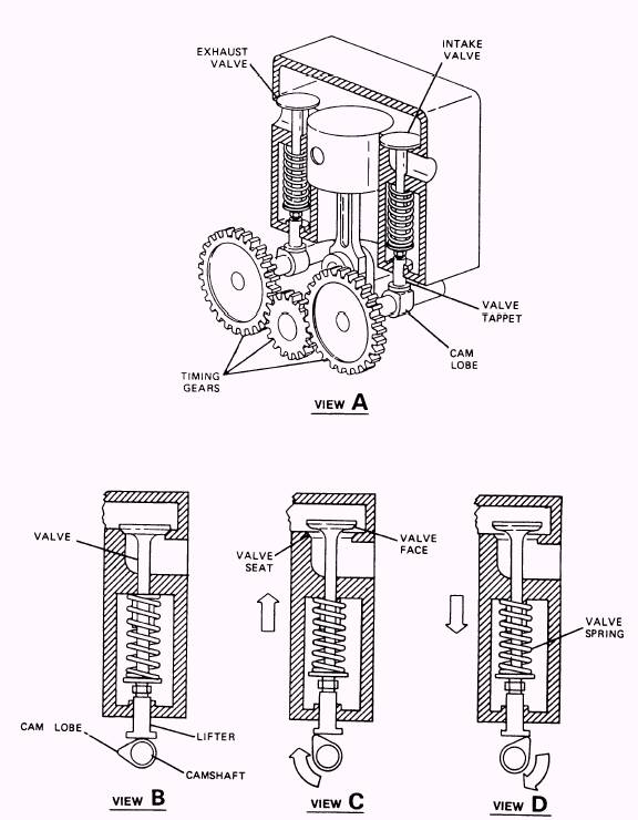
Figure 1-15.-Valve train operation.
Figure 1-16.-Common fuel tank locations. bum. The engine is fitted with a valve train to operate the valves, as shown in figure 1-15. The camshaft is made to rotate with the crankshaft through the timing gears. The cam lobe is the raised portion on the camshaft that contacts the bottom of the lifter. As the cam rotates, the lobe pushes up on the lifter. The cam lobe pushes the valve open against the pressure of a spring. As the cam lobe rotates away from the lifter, the valve spring pulls the valve closed. The proper positioning of the cam lobes on the camshaft establishes a sequence for the intake and exhaust valves. |
||
|
||