| Tweet |

Custom Search
|
|
 
|
||
|
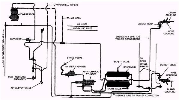
AIR-OVER-HYDRAULIC BRAKE SYSTEM An air-over-hydraulic brake system is shown in figure 3-47. This system combines the use of compressed air and hydraulic pressure for brake operation. The air-over-hydraulic brake system has an air-over-hydraulic power cylinder (fig. 3-48) that contains an air cylinder and a hydraulic cylinder in tandem. Each cylinder is fitted with a piston and a common rod. The air piston is of greater diameter than the hydraulic piston. This difference in the two pistons
Figure 3-47.-Typical air-over-hydraulic brake system.
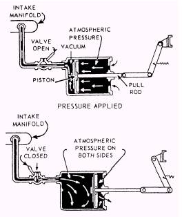
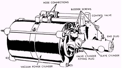
Figure 3-49.-Typical vacuum brake cylinder. results in much greater hydraulic pressure than air pressure admitted to the air cylinder. Valve action varies with the amount of pressure applied to the brake pedal. When heavy brake pedal pressure is applied by the operator for hard braking, the hydraulic pressure in the master cylinder (which operates the valves) causes greater valve movement. As a result, the valve admits more air pressure into the air-over-hydraulic power cylinder and this higher air pressure causes a stronger braking action. VACUUM BRAKES In a vacuum brake system, depressing the brake pedal opens a valve between the power cylinder, which contains a piston, and the intake manifold to which the power cylinder is connected (fig. 3-49). When you apply the brakes, air is exhausted from the cylinder head of the piston. At the same time, atmospheric pressure acts on the rear side of the piston to exert a powerful pull on the rod attached to the piston. When the brake valve is closed, the chamber ahead of the piston is shut off from the intake manifold and is opened to the atmosphere. The pressure is then the same on both sides of the piston; therefore, no pull is exerted upon the pull rod. The brakes are released and the piston returned to its original position in the power cylinder by the brake shoe return springs. HydrovacTM is a trade name for a one-unit vacuum power-braking system. It combines a hydraulic control valve, a vacuum power cylinder, and a hydraulic slave cylinder into one assembly. This assembly (fig. 3-50) is connected to both the master cylinder and the wheel brakes and eliminates the need for mechanical connections with the brake pedal. Pressure on the brake pedal forces fluid from the master cylinder through the check valve to the slave cylinder and to the wheel cylinders. Also, the foot pedal pressure, acting through the master cylinder, acts also against the slave cylinder piston to help the vacuum pistons and pushrods to press against the brake shoes.
Figure 3-50.-HydrovacTM power brake cylinder. |
 |
|
|
||