| Tweet |

Custom Search
|
|
 
|
||
|
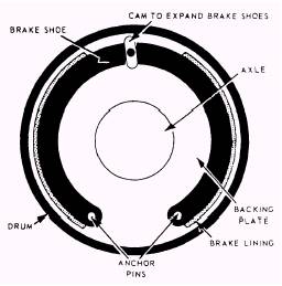
Internal Expanding Brakes Internal expanding brakes are used almost exclusively as wheel brakes, but can be found on some cranes. This type of brake permits a more compact and economical construction. The brake shoes and brake-operating mechanism are supported on a backing plate or brake shield attached to the vehicle axle, as shown in figure 3-40. The brake drum, attached to the rotating wheel, acts as a cover for the shoe and operating mechanism and furnishes a frictional surface for the brake shoes. The brake shoe of an internal expanding brake is forced outward against the drum to produce the braking action. One end of the shoe is hinged to the backing plate by an anchor pin, while the other end is unattached and can be moved in its support by the operating mechanism. When force from the operating mechanism is applied to the unattached end of the shoe, the shoe expands and brakes the wheel. A retracting spring returns the shoe to the original position when braking action is no longer required. Disc Brakes The disc brake has a metal disc (rotor) and a pair of flat brake pads instead of a drum and curved brake
Figure 3-40.-Internal expanding brake.
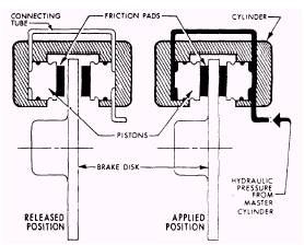
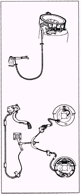
Figure 3-41.-Sectional view of a disc brake. shoes. Figure 3-41 shows a sectional view of a disc brake assembly. The two flat pads are on the two sides of the disc. The assembly in which the flat pads are held is the caliper assembly. In operation, the pads are forced against the two sides of the disc by the movement of the pistons in the caliper assembly. The pistons are actuated by hydraulic pressure from the master cylinder. The effect is to clamp the rotating disc between the stationary pads, as shown in figure 3-41. Mechanical Parking Brake In most vehicles, a hand lever or foot pedal engages the parking brake. The parking brake has its own system and can be either an external contracting brake bands on the drive shaft (fig. 3-42, view A) or a mechanical linkage that works the rear wheel brakes (fig. 3-42, view B). A hydraulic brake system is primarily a liquid connection or coupling between the brake pedal and the individual brake shoes and drums, as shown in figure
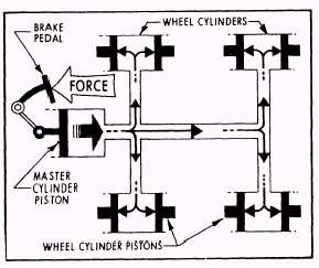
Figure 3-42.-Parking brake configurations. 3-43. The system consists of one master cylinder connected by pipes and flexible tubing to the wheel cylinders. The wheel cylinders control the movement of the brake shoes at each wheel. When the brake pedal is depressed, the hydraulic fluid forces the pistons in the wheel cylinder against the brake shoes, forcing the shoes against the brake drum or brake discs stopping the wheels. Hydraulic brakes are self-equalizing brakes. If the actuating pistons were all the same size, each brake in the hydraulic system would receive an identical hydraulic force when the brakes were applied, because a force exerted at any point upon a closed liquid is distributed equally through the liquid in all directions at the same time. All brake systems have larger wheel cylinders in the front than in the rear. When you stop a vehicle, more weight is automatically shifted forward due to inertia, so more front-wheel braking is required. The master cylinder is a reservoir for the brake fluid and contains pistons and valves which change mechanical force to hydraulic pressure when the brake pedal is depressed, as shown in figure 3-43. The pressure on the brake pedal moves the piston within the master cylinder to force the brake fluid from the master cylinder through tubing and flexible hoses to the wheel cylinders. As pressure on the pedal is increased, greater hydraulic pressure is built up within the brake cylinders, and thus greater force is exerted against the ends of the brake shoes. When pressure on the pedal is released, the retracting springs on the brake shoes return the wheel cylinder pistons to their released positions. This action forces the brake fluid back through the flexible hose and tubing to the master cylinder.
Figure 3-43.-Hydraulic brake system. The operation of a dual system master cylinder is basically the same as a single master cylinder. However, the dual system master cylinder has two separate hydraulic pressure systems. One of the hydraulic systems normally is connected to the front brakes and the other system to the rear brakes. If either the front or rear hydraulic system fails, the other system remains operational. The master cylinder, like other parts in the brake system, is subject to wear, leaks, and deposits or corrosion on the cylinder wall and piston. Part of your prestart operation is to check the cylinder reservoir fluid level and add clean brake fluid to maintain the manufacturer's specifications. The brake lines transmit fluid and pressure from the master cylinder to the wheel cylinders, which are mounted on the brake-backing plate, and change the hydraulic pressure into mechanical force. Inside each cylinder are two pistons that move in opposite directions by hydraulic pressure which pushes the brake shoes against the brake drum or disc. The brake shoes are made of steel that transmits force to the lining which is attached to the face of the shoe and makes contact with the brake drums or discs. During contact with one another, the lining and the drum or disc create the frictional surface that gives the braking effect. |
||
|
||