| Tweet |

Custom Search
|
|
 
|
||
|
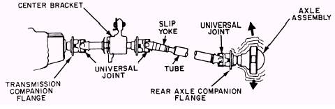
The propeller shaft assembly (fig. 2-12) consists of a propeller shaft, commonly know as the drive shaft, a slip joint, and two or more universal joints. This assembly provides a path through which power is transmitted from the transmission to the drive axle assemblies or auxiliary equipment. Vehicles, having a long wheel base, are equipped with a propeller shaft that extends from the transmission or transfer case to a center support bearing and a propeller shaft that extends from the center support bearing to the rear axle (fig. 2-13).
Figure 2-12.-Propeller shaft assembly.
Figure 2-13.-Propeller shaft assembly with center support bearing. Propeller shafts may be solid or tubular type and require little or no maintenance. Solid shafts are normally used where high shaft speeds are unnecessary. They are used extensively to power auxiliary equipment, such as winches and hydraulic pumps. The hollow shaft is used almost exclusively to transmit power to the axles on automotive vehicles. The hollow shaft, because it rotates at high speed, must be balanced to prevent vibration and premature bearing failure in the transmission and differential assemblies. A slip joint at one end of the propeller shaft takes care of end play. The driving axle, attached to the springs, is free to move up and down, while the transmission is attached to the frame and cannot move. Any upward or downward movements of the axle causes the suspension springs to flex. This action shortens or lengthens the distance between the axle assembly and the transmission. The slip joint makes up for this changing vertical distance. The type of slip joint normally used consists of a splined stub shaft, welded to the propeller shaft, that fits into a splined sleeve in the universal joint, as shown in figure 2-12. UNIVERSAL JOINTS A universal joint acts as a flexible coupling between two shafts and permits one shaft to drive another shaft that is at an angle to it. The universal joint is flexible in the sense that it permits power to be transmitted, while the angle of the shaft is being continually changed. A conventional universal joint assembly is composed of three fundamental units: a journal (cross) and two yokes, as shown in figure 2-12. The two yokes are set at right angles to each other and are joined by the journal. This design permits each yoke to pivot on the journal, allowing the transmission of rotary motion from one yoke to the other. As a result, the universal joint can transmit power from the engine through the shaft to the drive axle, even when the engine is mounted in the frame at a higher level than the drive axle, as shown in figure 2-13. Universal joints need little, if any, maintenance other than lubrication. Some universal joints have grease fittings and should be lubricated according to the manufacturer's specifications. |
||
|
||