| Tweet |

Custom Search
|
|
 
|
||
|
A compressor is a machine that compresses air from an initial intake pressure to a higher exhaust pressure through a reduction in volume. A compressor consists of a power source, a compressor unit, and accessory equipment. A gasoline or diesel engine provides power to operate the compressor. Most compressors, used in the NCF, are governed by a pressure control system, adjusted to compress air to a maximum pressure of 100 pounds per square inch (psi). Compressor units are available in reciprocating, rotary, or screw design. Compressors are classified as either single-stage or multistage. A single-stage compressor has one compressing element that compresses the air from the initial intake pressure to the final discharge pressure in one step. The multistage compressor has more than one compressing element. The first stage compresses the air to an intermediate pressure, then through one or more additional stages to final discharge pressure. The multistage system is more efficient than the single-stage system, because the air cooling that occurs between stages reduces buildup of pressure due to a temperature rise. All military construction compressors are governed by a pressure control system. In a reciprocating compressor, this control system causes the engine to idle and the suction valve to remain open when the pressure reaches a set maximum. When the air pressure drops below a set minimum, the pressure control system causes the engine to increase speed and the suction valve to close, starting the compression cycle again. The rotary compressor output is governed by varying the engine speed. The engine operates automatically at the speed needed to compress enough air to supply the demand at a fairly constant pressure. When the engine has slowed to idle because of low demand, a valve throttles the amount of free air that may enter the compressor. The screw compressor output is controlled automatically and provides a smooth, uninterrupted capacity from full load to no load in response to the demand for air. This capacity is achieved by a floating speed engine control and a variable inlet compressor. The capacity of an air compressor is determined by the amount of free air (at sea level) that it can compress to a specified pressure, usually 100 psi per minute, under the conditions of 68F and a relative humidity of 38 percent. This capacity is expressed in cubic feet per minute (cfm) and is usually included in the nomenclature of the compressor. The number of pneumatic tools that can be operated at one time from an air compressor depends on the air requirements of each tool; for example, a 55-pound class rock drill requires 95 cfm of air at 80 psi. A 210-cfm compressor can supply air to operate two of the drills, because their combined requirements is 190 cfm. However, if a third such drill is added to the compressor, the combined demand is 285 cfm, and this condition overloads the compressor and the tools and results in serious wear. NOTE: When the pressure and volume of air to a pneumatic tool drops 10 percent below the designed minimum, the tool efficiency is reduced 41 percent. Compressor Location Install the compressor unit so it is as close to level as possible. Compressor design permits a 15-degree lengthwise and a 15-degree sidewise limit on out-of-level operation. The engine, not the compressor, is the limiting factor. When the unit is to be operated out of level, you should be sure to do the following: 1. Keep the engine crankcase oil level on the full mark with the unit level. 2. Ensure the compressor oil gauge shows full with the unit level. A compressed air system consists of one or more compressors, each with the necessary power source, regulation, intake air filter, aftercooler, air receiver, connecting piping, and a distribution system to carry the air to points of use. The object of installing a compressed air system is to provide enough air at the work area at pressures adequate for efficient operation of pneumatic tools. Many construction jobs require more cfm than one compressor can produce. Also, terrain conditions often create problems of distance from the compressor to the operating tool. Since the air line hose causes a loss of pressure (friction loss) at distances farther than 200 feet, a system has been devised for efficient transmission of compressed air over longer distances. This system is air manifolding (fig. 14- 10).
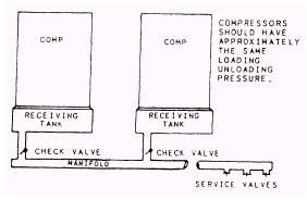
Figure 14-10.-Methods of manifolding compressors. An air manifold is a large-diameter pipe that transports compressed air from one or more compressors over considerable distances without friction line loss. In construction work, air manifolds are usually constructed of 6-inch-diameter pipe with check valves. A pipe of this size can carry 1,200 cfm of air (output from two 600-cfm air compressors) at 100 psi with less than 0.035-pound pressure loss per 100 linear feet. One or more compressors pump air into the manifold and then "pressurize" it at 100 psi. Air may then be used at any point along the manifold by installing outlet valves and connecting airlines to pneumatic tools. CAUTION Different types of compressors should not be used on the same manifold. The difference in pressure control systems of a rotary, a reciprocating, and a screw compressor could cause one compressor to be overloaded, while the other is idled. Any drop in pressure between the compressor and the point of use is a permanent loss. Because of this, the air distribution system is an important element of the compressed air system. When planning the air system, you should observe the following steps: . Pipe size should be large enough to ensure the pressure drop between the compressor and the point of use does not exceed 10 percent. . Extremely long distribution lines should have air receivers near the far ends or at points of occasional heavy use. Many peak demands for compressed air are only for an instant, and storage capacity near such points prevents an excessive drop in line pressure. . Each header or main should be provided with outlets as close as possible to the point of use to permit shorter hose lengths and to avoid large pressure drops through the hose. Outlets should always be located at the top of the pipeline to prevent carry-over of condensed moisture to the tool. Condensate drains should be positioned correctly along the header or main line. SAFETY General safety precautions for air compressors are as follows: . Be sure the intake air is cool and free from flammable gases or vapors. l Do NOT permit flammable materials to touch the air discharge pipe. l Never operate a compressor that has faulty gauges. l Never kink a hose to stop the air flow, and keep the hose clamps on tight. . Before starting an air compressor, check the safety valves, pressure valves, and regulators to see that they are working properly. . Do NOT leave the compressor after starting it unless you are sure the control, unloading, and governing devices are working properly. . Do NOT run an air compressor faster than the speed recommended by the manufacture. l Use only the grade and amount of oil recommended by the manufacturer. Use only high flash point oils to lubricate the air cylinders of air compressors. . Keep compressors, tanks, and accompanying piping clean to guard against oil vapor explosion. Clean intake air filters regularly. l Use only soapy water or a suitable nontoxic, nonflammable solution for cleaning compressor intake filters, cylinders, or air passages. Never use benzene, kerosene, or other light oils to clean these parts. These oils vaporize easily and form a mixture that is highly explosive under compression. . Secure the engine before adjusting and repairing an air compressor. . Before working on or removing any part of a compressor, make certain that the compressor is secured and cannot be started automatically or accidentally and that the air pressure in the compressor is relieved completely. Also, ensure that all valves between the compressor and receivers are closed. l Be careful with compressed air. At close range, it can put out eyes, burst eardrums, and cause serious skin burns. Always wear impact goggles or safety glasses and dual-hearing protection when using compressed air. NEVER use compressed air to blow dust off clothing, skin, or hair. l When transporting a compressor or any other towed unit, ensure the pulling unit meets specifications. This includes drawbar horsepower and height of towing pintle (not too high or low because it can damage the towing tongue). Ensure all electrical hookups fit and are the right length. l When parking, ensure the parking brake is applied and wheels are chocked. . Safety chains must be of proper size and length and secured properly (fig. 14- 11). |
 |
|
|
||