| Tweet |

Custom Search
|
|
 
|
||
|
Moldboard The moldboard with the cutting edge and end bits attached is called the blade. The blade is the working
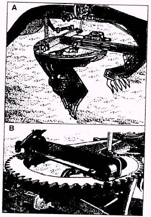
Figure 10-6.-Moldboard.
Figure 10-7.-Blade heel and toe. tool of the grader that can be lifted, lowered. rotated. tilted forward and backward, shifted to one side or the other, and angled horizontal (fig. 10-6). The cutting edge and end bits are bolted to the moldboard. They act as wear plates and must be replaced or reversed when worn or broken. In most cases, the bolts will have to be replaced too. NOTE: Always keep enough cutting edges and end bits on hand to protect the moldboard from wear or damage. The length of the blade is normally 12 or 14 feet. The curve shape of the blade causes dirt to roll and mix, as it is cut and moved. The rotary movement of the dirt combined with the angle of the blade causes a side-cast drift of the material. When the blade is angled to position one end ahead of the other, two terms are used to designate the blade ends. They are the heel and the toe of the blade. Figure 10-7 shows that the toe is the leading edge of the blade;
Figure 10-8.-Circle. the heel is the trailing edge. When the blade is turned so the toe is to your left, as you sit in the operator's seat, the material will side cast to your right and spill
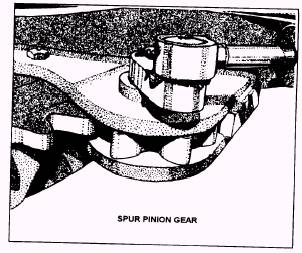
Figure 10-9.-Spur-pinion gear.
Figure 10-10.-Drawbar.
Figure 10-11.-Ball-and-socket connection. off the heel. When the toe of the blade is to your right, the material will side cast to the left and spill off the heel. The moldboard is supported and held in position by curved brackets, called circle knees and side shift guides, as shown in figure 10-6. They are attached to the underside of a rotatable ring, called the circle. Cycle The circle is a tooth-ring gear that is rotated in a supporting frame by the circle reverse mechanism. The circle teeth may be internal (fig. 10-8, view A) or external (fig. 10-8, view B), depending on the make and model of the grader. The circle is turned by a spur-pinion gear (fig. 10-9) that meshes with the circle teeth. The spur-pinion gear is held by the drawbar and is controlled by a lever in the operator's cab. Engaging the spur-pinion gear allows rotating the circle to the desired blade angle position. Drawbar The drawbar is a V- or T-shaped connection between the front of the grader frame and the circle (fig. 10-10). The drawbar holds the circle rigid and is fastened by a ball and socket that allows angular movement from side to side and up and down (fig. 10-11). The drawbar carries the full-horizontal load on the blade. Other components provide vertical and side support. Scarifier The scarifier is a hydraulically controlled unit with a set of teeth used to break up material too compacted
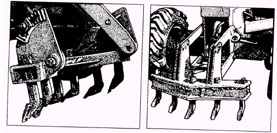
Figure 10-12.-Scarifiers. to be penetrated by the blade. The scarifier is either pulled or pushed through the material, depending on the make and model of the grader and the position of the scarifier unit on the equipment. Figure 10-12 shows two types and locations of scarifies on graders. The teeth, consisting of slender shanks with replaceable caps, are set in a V-shaped bar (fig. 10-13). The shanks are wedged or clipped in place and maybe adjusted for height or removed completely. A scarifier with all the teeth is used for shallow penetration and light work. For hard or deeper penetration, remove every other tooth. |
||
|
||