| Tweet |

Custom Search
|
|
 
|
||
|
STOP
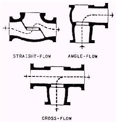
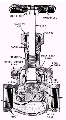
VALVES Stop valves are used to shut off or, in some cases, control the flow of fluid. They are con-trolled by the movement of the valve stem. Stop valves can be divided into four general categories: globe, gate, butterfly, and ball. (Plug valves and needle valves are also considered to be stop valves, but they are covered in more detail in Fireman, NAVEDTRA 10520-H.) Globe Valves Globe valves are probably the most common valves in existence. They are used throughout the engineering plant and other parts of the ship. The globe valve gets its name from the globular shape of the valve body. However, you have to look in-side the valve for a positive identification because other valve types may also have globular bodies. Globe valve inlet and outlet openings are arranged in several ways to suit varying requirements of flow. Figure 13-17 shows the common types; straight flow, angle flow, and cross flow. Figure 13-18 shows a cutaway view of a straight-flow globe valve. Gate Valves Gate valves are used when a straight line flow of fluid and minimum flow restriction are needed, such as in the inlet piping for a centrifugal pump. Gate valves are so named because the part that either stops or allows flow through the valve acts somewhat like the opening or closing of a gate and is called, appropriately, the gate. The gate is usually wedge-shaped. When the valve is wide open the gate is fully drawn up into the valve bonnet. This leaves an opening for flow through the valve the same size as the pipe in which the valve is installed. Therefore, there is little pressure drop or flow restriction through the valve. Gate valves are not suitable for throttling purposes. The control of flow would be difficult because of valve design, and the flow of fluid slapping against a
Figure 13-17.-Types of globe valve bodies.
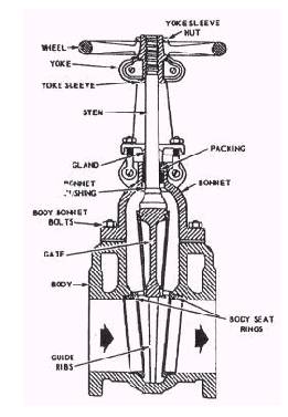
Figure 13-18.-Cutaway view of a straight-flow globe valve. partially open gate can cause extensive damage to the valve. Except as specifically authorized, gate valves should not be used for throttling. Gate valves are classified as either rising-stem or nonrising-stem valves. The rising-stem valve is shown in figure 13-19. In the design of the rising-stem valve, the stem is attached to the gate. The gate and stem rise and lower together as the valve is operated. In the design of the nonrising-stem gate valve, the stem is threaded on the lower end into the gate. As the handwheel on the stem is rotated, the gate travels up or down the stem on the threads while the stem remains vertically stationary. This type of valve will almost always have a pointer type of indicator threaded onto the upper end of the
Figure 13-19.-Cutaway view of a gate stop valve (rising stem). stem to indicate the position of the gate inside the valve. |
||
|
||