| Tweet |

Custom Search
|
|
 
|
||
|
ELECTROHYDRAULIC
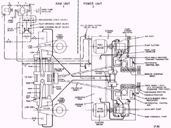
STEERING GEAR The direction of a ship moving through the water is controlled by changing the angle of its rudder(s), located in the stern of the ship. As the gross tonnage of ship increases, more and more force is required to move the rudder(s) through the required angle. On a large ship, the power required to position the rudder is provided by one or more electrohydraulic steering engines which respond to rudder orders transmitted electrically from the helm (steering wheel) in the pilot house to the steering gear, located directly above the rudder(s) in the stern. The steering engine or gear transmits power from the steering engine to the rudder stock. The term steering gear normally includes the driving engine and the transmitting mech-anism. Although several different designs of steering engines are in common use, their operating principles are similar. One example of an electrohydraulic steering engine for a ship with two rudders is shown in figure 18-2. It
Figure 18-2.-Electrohydraulic steering engine. consists essentially of (1) a ram unit and (2) a power unit. Ram Unit Refer to section 1 in figure 18-2. The ram unit is mounted athwartship (from side to side) and consists of a single ram (piston) between opposed cylinders. The ram is connected by links to the tillers of the twin rudders. When oil pressure is applied to one end of the operating cylinder, the ram will move, causing each rudder to move along with it. Oil forced out of the cylinder at the other end of the ram returns through ports in the transfer valve to the suction side of the main hydraulic pump of the power unit that is on line. (Oil supply and return piping is shown by wider black lines in fig. 18-2.) Power Unit Refer to section 2 of figure 18-2. The power unit consists of two independent pumping systems. Two systems are used for reliability. One pump can be operated while the other is on standby. Each pumping unit consists of a variable-delivery, axial-piston main pump and a vane-type auxiliary pump. Both are driven by a single electric motor through a flexible coupling. Each system also includes a transfer valve with operating gear, relief valves, a differential control box, and trick wheels. The whole unit is mounted on a bedplate, which serves as the top of an oil reservoir. Steering power is taken from either of the two independent pumping units. The pumps of the power unit are connected to the ram cylinders by high-pressure piping. The two transfer valves are placed in the piping system to allow for the lineup of one pump to the ram cylinders with the other pump isolated. A hand lever and mechanical linkage (not shown) are connected to the two transfer valves in such a way that both valves are operated together. This allows for rapid shifting from the on-service pumping unit to the standby unit; it also prevents both pumps from being lined up to the ram at the same time. The hand lever is usually located between the trick wheels. It has three positions marked P, N, and S. P denotes the port pump connected to the ram; N denotes neutral (neither pump connected to the ram); and S denotes the starboard pump connected to the ram. Also, the hand lever is usually connected to motor switches. This permits the operator to connect the selected pump to the ram and start the pump drive motor in one quick operation. In most modern ships this valve is electrically controlled by the motor controller and by pressure switches. |
||
|
||