| Tweet |

Custom Search
|
|
 
|
||
|
PRECOMBUSTION
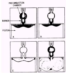
AND TURBULENCE Some diesel engines have an auxiliary space or chamber at or near the top of each main combustion space. These chambers receive all or part of the injection fuel and condition it for final combustion in the main combustion chamber of the cylinder. This conditioning, called pre-combustion, involves a partial burning of the fuel before it enters the main combustion space. Precombustion helps to create the turbulence needed for the fuel and air to be properly mixed. Because of differences in designs, the manner in which precombustion aids in creating turbulence differs from one type of auxiliary combustion chamber to another. For this reason, we will discuss three types of auxiliary chambers by their common names-PRECOMBUSTION
Figure 9-1.-Precombustion chamber. CHAMBERS, TURBULENCE CHAMBERS, and AIR or ENERGY CELLS. Look at figure 9-1 to see how the pre-combustion chamber creates turbulence. The precombustion chamber, spherical in shape, is located in the cylinder head directly over the center of the piston crown. The precombustion chamber is connected to the main combustion space of the cylinder by a multiple orifice called a burner. During the compression event, a relatively small volume of compression-heated air is forced through the burner into the precombustion chamber. Heat stored by the burner increases the temperature of the compressed air and facilitates initial ignition. Fuel is atomized and sprayed into the hot air in the precombustion chamber (view A) and combustion begins (view B). Only a small part of the fuel is burned in the precombustion chamber because of the limited amount of oxygen. The fuel that does burn in the chamber creates enough heat and pressure to force the fuel, as injection continues, into the cylinder at great velocity (view C). The velocity of the fuel entering the main combustion space and the shape of the piston crown help to create the necessary turbulence within the cylinder (view D). Engines that have precombustion chambers do not require fuel injection pressures as great as engines that have open-type chambers. Also, the
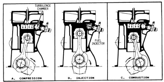
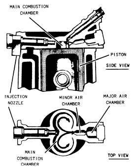
Figure 9-2.-Turbulence chamber. spray of injected fuel can be coarser, since the precombustion chamber functions to atomize the fuel further before the fuel enters the cylinder. Some engines have auxiliary combustion chambers. They differ from precombustion chambers in that nearly all of the air supplied to the cylinder during the intake event is forced into the auxiliary chamber during the compres-sion event. Auxiliary chambers in which this occurs are sometimes referred to as TURBU-LENCE CHAMBERS. There are several varia-tions of turbulence chambers, one of which is illustrated in figure 9-2. Note in figure 9-2 how turbulence, indicated by the arrows, is created in the auxiliary chamber as compression (view A), injection (view B), and combustion (view C) take place. In engines with turbulence chambers, there is very little clearance between the top of the piston and the head when the piston reaches TDC. (See view B of fig. 9-2.) For this reason, a high percentage of the air in the cylinder is forced into the turbulence chamber during the compression event. The shape of the chamber (usually spherical) and the size of the opening through which the air must pass help to create turbulence. The opening to the turbulence chamber becomes smaller as the piston reaches TDC, thereby increasing the velocity of the air. Velocity plus deflection of the air as it enters the auxiliary chamber creates considerable turbulence. Fuel injection (view B of fig. 9-2) is timed to occur when the turbulence in the chamber is the greatest. This ensures a thorough mixing of the air and fuel. The greater part of combustion takes place within the turbulence chamber and is completed as the burning gases expand and force the piston down in the power event. In some high-speed diesel engines, turbulence is created by an auxiliary chamber referred to as an ENERGY (AIR) CELL. Energy cells differ in design and location. In most engines, the cells are located in the cylinder heads. One type of energy cell that is located in the cylinder head is a divided chamber and turbulence chamber. The Lanova cell is the divided chamber type. Figure 9-3 shows cross-sectional top and side views of a divided auxiliary combustion chamber. Refer to figure 9-3 as we discuss how the energy cell system works. Study the construction and operation of a typical system, the Lanova design, shown in figure 9-3. This design employs a combustion chamber consisting of two rounded spaces cast in the cylinder head. The inlet and exhaust valves open into the main combustion chamber. The fuel-injection nozzle lies
Figure 9-3.-Divided combustion chamber. horizontally, pointing across the narrow section where the lobes join. Opposite the nozzle is the two-part energy cell, which contains less than 20 percent of the main-chamber volume. The action is as follows: During the com-pression stroke, the piston forces air into the energy cell. Near the end of the stroke, the nozzle sprays fuel across the main chamber in the direction of the mouth of the energy cell. While the fuel charge is traveling across the center of the main chamber, between a third and a half of the fuel mixes with the hot air and burns at once. The remainder of the fuel enters the energy cell and starts to burn there, being ignited from the fuel already burning in the main chamber. At this point, the cell pressure rises sharply, causing the products of combustion to flow at high velocity back into the main combustion space. This sets up a rapid swirling movement of fuel and air in each lobe of the main chamber, promoting the final fuel-air mixing and ensuring complete combustion. The two restricted open-ings of the energy cell control the time and rate of expulsion of the turbulence-creating blast from the energy cell into the main combustion space. Therefore, the rate of pressure rise on the piston is gradual, resulting in smooth engine operation. The divided combustion chamber is similar, in some respects, to other types of chambers. It is similar to an open combustion chamber in that the main volume of air remains in the main com-bustion chamber and principal combustion takes place there. Both the divided chamber and the turbulence chamber depend on a high degree of turbulence to ensure thorough mixing and distribution of the fuel and air. However, turbulence in a divided combustion chamber is dependent on thermal expansion caused by combustion in the energy cell and not on engine speed as in other types of auxiliary combustion chambers. |
||
|
||