| Tweet |

Custom Search
|
|
 
|
||
|
TURBOCHARGER.-Turbochargers
are unlike positive displacement blowers, which are driven through a gear train
by the engine crankshaft. Positive displacement blowers permit only modest
power increases since most of the power developed must be returned to drive the
blower. On the other hand, turbochargers produce higher net gains as they use
the normally wasted exhaust gas energy for power. Turbo-charging can produce
power gains of over 50% compared to those of naturally aspirated engines. In
brief, the principles of operation of a turbocharger are as follows: (1) the
gases from the exhaust manifold drive a turbine, and (2) the turbine drives an
impeller (on the same shaft), which supplies air to the cylinders for scavenging
and supercharging. There are several
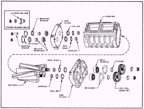
Figure 6-9.-Components of a roots type of blower.
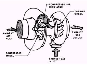
Figure 6-10.-Principles of operation for a turbocharger. types of centrifugal blowers (turbochargers) in naval service. They all, however, operate on this basic principle. In our discussion of the turbocharger we will stay with a general description because there are many different types of turbochargers in use within the Navy. Figure 6-10 provides an illustra-tion of a turbocharger. You should refer to figure 6-10 as you read the following information. The exhaust system of a turbocharger consists of a heat-resistant alloy casting that encloses the turbine wheel and provides an exhaust gas inlet and an exhaust gas outlet. The system furnishes the driving power for the turbocharger by using the high-temperature and high-velocity exhaust gases from the exhaust manifold. The gases enter the turbine casing, striking the turbine wheel and causing it to rotate at a high speed. The speed of the turbine is automatically controlled by the speed and the load of the engine. When the gases have turned the turbine, they are discharged through the exhaust outlet. The air-intake system of a turbocharger consists of a compression housing and compressor wheel. (Refer to fig. 6-10.) During engine operation, exhaust gases flowing from the engine through the turbine housing cause the turbine wheel to rotate. The compressor wheel, which is mounted on the opposite end of the same shaft, rotates with the turbine. The compressor wheel draws ambient (fresh) air into the compressor housing and compresses the air. The turbocharger responds to engine load change by reacting to the flow of exhaust gases. As the power output of the engine increases, the flow of exhaust gases also increases. This action increases the speed and out-put of the rotating assembly proportionately,
Figure 6-11.-Air induction and exhaust system (Caterpillar D-399 engine). delivering more air to the intake system of the engine. Figure 6-11 illustrates the air induction and ex-haust system for one type of diesel that uses two turbochargers. Note the arrows that indicate the flow pattern of the exhaust, inlet air, and com-pressed air systems. As indicated in figure 6-11, the compressed air used for combustion and scavenging is directed through an AFTER-COOLER. Most engines that are turbocharged use aftercoolers to cool the compressed air. Aftercoolers, also referred to as HEAT EX-CHANGERS, are small radiators placed between the compressor housing and the intake manifold of the engine. As the compressed hot air passes through the aftercooler, the air is cooled to reduce its volume. Consequently, more air is able to enter the cylinder. The result is lower cylinder pressure, more effective cooling of the cylinder component, and a lower exhaust temperature. Without the aftercooler, the air temperature entering the intake manifold will increase sharply because of the compression of the air and heat from the turbocharger. This undesirable condition would result in a loss of air density and power, a higher temperature within the cylinder, and a higher exhaust gas temperature. In some installations, roots blowers and turbo-chargers are used together within one system. These two components serve to compress the air more efficiently than would be possible if only a blower or a turbocharger were to be used separately. As we discuss this type of system, refer to figure 6-12.
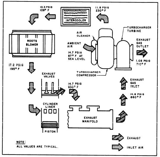
Figure 6-12.-Engine air system with roots blower and turbocharger assemblies (General Motors 16 V series 149). In operation, air is drawn into the blower section of the turbocharger through the air cleaner. Air is compressed and the temperature is increased. The high-temperature compressed air is then delivered to the intercooler (heat exchanger), where the temperature is reduced. (Intercoolers are heat exchangers that are usually located between the compressor and the roots blower.) The cooled dense charge of air is then routed to the roots blower inlet. The roots blower further compresses the air and delivers it to the engine. During the intake event, air is forced into the cylinders where it scavenges (cleans) out the combustion gases and fills the cylinder with a clean, dense air charge that is above atmospheric pressure. After the combustion and power event are completed, the exhaust valves open and the hot exhaust gases are discharged to the exhaust manifold. The hot, high-velocity exhaust gases are directed to the turbine section of the turbochargers where they drive the turbine wheel at high speed. During this process, the pressure and the temperature of the exhaust gases are reduced and some of the energy that would otherwise be lost is used to drive the turbocharger. After the exhaust gases leave the turbocharger, they are routed to a muffler. Even though brief and very general, the preceding account of turbochargers and blowers should sufficiently clarify the principles of operation. The details and specific instructions for a turbocharger, a blower, or any other component in an engine should be obtained from the manufacturers technical manual. |
||
|
||