| Tweet |

Custom Search
|
|
 
|
||
|
OPPOSED-PISTON ENGINES
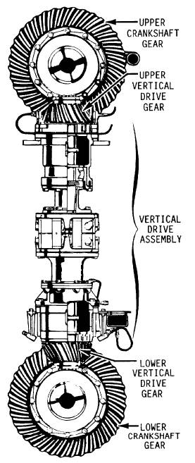
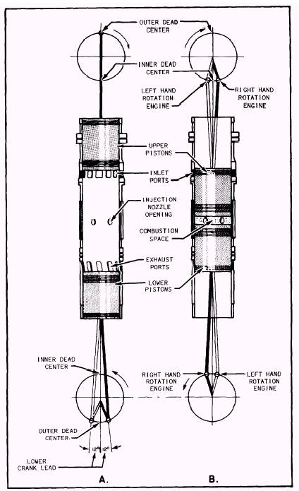
With respect to the combustion-gas action, the term OPPOSED-PISTON identifies those engines that have TWO PISTONS and ONE COMBUSTION SPACE in each cylinder. (Refer to fig. 2-10.) The pistons are arranged in opposed positions; that is, crown to crown, with the combustion space in between. When combustion takes place, the gases act against the crowns of both pistons, driving them in opposite directions. Thus, the term opposed not only signifies that the gases act in opposite directions (with respect to pressure and piston surfaces), but also classifies piston arrange-ment within the cylinder. In engines that have the opposed-piston arrangement, two crankshafts (upper and lower) are required for transmission of power. Both shafts contribute to the power output of the engine. In opposed-piston engines that are common to Navy service, the crankshafts are connected by a vertical gear drive which provides the power developed by the upper crankshaft. This power is delivered through the vertical drive shaft to the lower crank-shaft. Large roller bearings and thrust bear-ings support and guide the vertical drive shaft. (See fig. 2-11.) The cylinders of opposed-piston engines do not have valves. Instead, they employ scavenging air ports located near the top of the cylinder. (Refer to fig. 2-10.) These ports are opened and closed by the upper piston. Exhaust ports,located near the bottom of the cylinder, are closed and opened by the lower piston. Movement of the opposed pistons is such that the crowns are closest together near the center of the cylinder. When in this position, the pistons are not at the true piston dead centers. This is because the lower crankshaft operates a few degrees in advance of the upper shaft. The number of degrees that a crank on the lower shaft travels in advance of the corresponding crank of the upper shaft is called LOWER CRANK LEAD. (Refer to fig. 2-12.) Note in view A of figure 2-12 that the lower crankshaft is 12 degrees past outer dead center (ODC), when the upper piston is ON outer dead
Figure 2-11.Vertical drive assembly in a Fairbanks-Morse opposed-piston engine. center. In other words, the lower shaft leads the upper shaft by 12 degrees of rotation. Outer dead center (ODC) and inner dead center (IDC) of an opposed piston engine correspond, respectively, to BDC and TDC of single-acting engines.
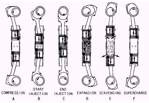
Figure 2-12.Lower crank lead in an opposed-piston engine. In view B of figure 2-12, the lower shaft is shown a few degrees past IDC and the upper shaft the same number of degrees before IDC. (Keep in mind that the upper and lower shafts rotate in opposite directions.) With the shafts at these positions, the pistons are closest together and are sometimes referred to as being at COMBUSTION DEAD CENTER. Note that the midpoint between the shaft positions is piston dead center. Opposed-piston engines used by the Navy operate on the 2-stroke cycle. In engines of the opposed-piston type, as in 2-stroke cycle single-acting engines, there is an overlap of the various events occurring during a cycle of operation. INJECTION and the burning of the fuel start during the latter part of the COMPRESSION event and extend into the POWER phase. There is also an overlap of the EXHAUST and SCAVENGING periods. The events in the cycle of operation of an opposed-piston, 2-stroke, diesel engine cycle are shown in figure 2-13. In view A of figure 2-13, the cylinder is charged with air and the pistons are moving toward IDC. Since the scavenging air ports are covered by the upper piston and the exhaust ports are covered by the lower piston, COMPRESSION is taking place. A few degrees before the lower piston reaches IDC, fuel is injected, as represented in view B of the figure, and COMBUSTION occurs. Injection is completed, as indicated in view C, slightly before the pistons reach combustion dead center, where compression is highest. The combustion of the fuel almost doubles the pressure shortly after this point in the cycle. As the gases expand, as indicated in view D, the pistons are driven in opposite directions toward the ODCs, and power is transmitted to both crankshafts. As each of the pistons approaches ODC, the lower piston uncovers the exhaust ports to allow the waste gases to escape from the combustion space. Then, the upper piston uncovers the scavenging air ports, as in view E. The flow of scavenging air forces the remaining gases out of the cylinder. Next, the lower piston covers the exhaust ports, as indicated in view F, and air continues to fill the cylinder until the upper piston covers the scavenging air ports. Thus, the cycle is completed. In the cycle of operation just described, the exhaust ports are uncovered (view E) and covered (view F) slightly before the intake ports are opened and closed because of the lower crankshaft lead.
Figure 2-13.Events in an operating cycle of an opposed-piston engine. Lower crank lead influences scavenging as well as power output. Since the intake ports are open for a brief interval after the exhaust ports close, air can be forced into the cylinder at a pressure above that of the atmosphere. (In other words, the cylinder can be supercharged.) This feature results in the development of more power than would be possible if pressure were normal. Crank lead also results in less power being delivered to the upper shaft than to the lower shaft. The amount of power transmitted to each crankshaft differs because, by the time the upper piston reaches IDC after INJECTION and COMBUSTION, the lower piston has already entered the POWER phase of the cycle. The lower piston, therefore, receives the greater part of the force created by COMBUSTION. In other words, by the time the upper piston reaches IDC and begins to transmit power, the volume of the gases has already begun to increase. Therefore, the pressure acting on the upper piston is less than the pressure that was acting on the lower piston when it began to deliver power. The amount of power delivered by the lower crankshaft varies with the engine model. In some engines, from 70 to 80 percent of the total power output is delivered by the lower crankshaft. The power available from the upper shaft is already less than that from the lower shaft power because of lower crank lead. The power from the upper shaft is further reduced insofar as engine output is concerned, by the load of the engine accessories which the upper shaft generally drives. Modern engines of the opposed-piston design have several advantages over single-acting engines of comparable rating. Some of these advantages are less weight per horsepower developed, lack of cylinder heads and valve mechanisms (and the cooling and lubricating problems associated with them), and fewer moving parts. Single-acting engines have their own advan-tages, such as not requiring blowers, if they are of the 4-stroke cycle design. These engines are more efficient if they are supercharged with a turbocharger, which is driven by the otherwise wasted energy of exhaust gases. Certain repairs are easier on a single-acting engine since the combustion space can be entered without the removal of an engine crankshaft and piston assembly. |
||
|
||