| Tweet |

Custom Search
|
|
 
|
||
|
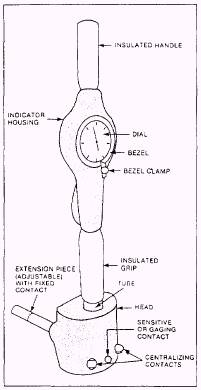
BORE GAUGES The dial bore gauge is one of the most accurate tools for measuring a cylindrical bore or for checking a bore for out-of-roundness or taper. The gauge does not give a direct measurement. It identifies the amount of deviation from a preset size or the amount of deviation from one part of the bore to another. A master ring gauge, outside micrometer, or vernier caliper can be used to preset the gauge. Figure 2-6 shows a typical bore gauge.
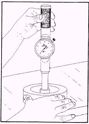
Figure 2-6.Typical bore gauge. Most bore gauges consist of a dial indicator, extension pieces, bezel and locknut, spring-loaded guide, and sensor button. Before you start a measuring procedure, expose both the bore gauge and the master ring gauge, or any other tools used to preset the bore gauge, and the part to be measured to the same work place environment for one hour. If you fail to do this, a temperature differential may cause your readings to be inaccurate. When you use the bore gauge, touch only its insulated handle. The gauge has two stationary spring-loaded points and an adjustable point to permit a variation in range. These points are evenly spaced to allow accurate centering of the tool in the bore. A fourth point, the tip of the dial indicator, is located between the two stationary points. By simply rocking the tool in the bore, you can observe the amount of variation on the dial. Figure 2-7 shows a bore gauge inside a bore being moved in a gentle rocking motion. Always follow the bore gauge manufacturers operating manual. Measure the bore and mark the areas you measure. A good
Figure 2-7.Measuring a bore with a bore gauge. practice is to check the bore gauge in the standard after you take each set of measurements to ensure that readings are accurate. |
||
|
||