| Tweet |

Custom Search
|
|
 
|
||
|
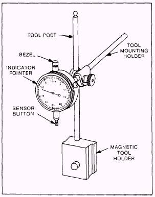
DIAL INDICATOR A dial indicator is used to measure shaft runout, shaft thrust, gear backlash, flywheel face runout, flywheel housing concentricity, and valve seat concentricity. You can mount a dial indicator on a test stand or, with clamps and a magnetic base, directly on the equipment to be measured. Figure 2-1 shows a typical dial indicator with mounting accessories, Most dial indicators have components such as a bezel, indicator pointer, tool post and clamp, magnetic toolholder, and sensor button that are used in taking measurements. The following procedures explain how to use the indicator to take shaft runout and crankshaft end play measurements. Procedures for taking other measurements are similar.
Figure 2-1.Typical dial indicator wlth mounting accessories. Shaft Runout When you need to measure a shafts runout, select a suitable position on the shaft, free of keyways, corrosion, or other damage. Clean the surface and remove any burrs around scratches or dents. To take the runout measurement, use the following procedure: 1. Place the shaft in well-oiled V-blocks. If the shaft is a crankshaft, place the bearing journals in the V-blocks. 2. Attach the magnetic base to a machined surface. Mount the dial indicator on a tool mounting holder and attach the holder to the base. 3. Adjust the mounting post so you can easily read the face of the dial. 4. Move the indicator toward the shaft until the sensor button just touches the surface you wish to measure. 5. Continue moving the indicator slowly toward the shaft until the dial pointer has moved to the midpoint of its travel on the dial face. 6. Leave the pointer at midtravel and turn the bezel until the zero on the dial is aligned with the pointer. 7. You can now rotate and watch the pointer to see if it moves. The total amount the pointer moves is called the total indicator reading (TIR). If the shaft is straight, the pointer should remain at zero. Crankshaft End Play or Thrust Readings To measure crankshaft end play or thrust, use the following procedure: 1. Attach the dial indicator to a convenient place near the vibration damper. 2. Position the dial indicator gauge so the contact point touches the front of the vibration damper and moves the dial indicator near the midpoint of its range. 3. Insert one end of a pry bar between a main bearing cap and a crankshaft counterweight. NOTE: DO NOT INSERT THE PRYBAR BETWEEN THE VIBRATION DAMPER AND THE BLOCK TO MEASURE THE CRANKSHAFT END PLAY. You may dent the damper and render it ineffective. 4. Move the crankshaft toward the dial indicator. Be sure to maintain a constant pressure on the prybar. 5. Set the dial indicator to zero. 6. Remove the prybar and then reinsert it on the other side of the main bearing cap. 7. Carefully pry the crankshaft in the opposite direction to measure the crankshaft end play. Repeat your measurement a minimum of two times for accuracy. |
||
|
||