Custom Search
|
|
 
|
||
|
CRANKSHAFTS Scored crankshaft journals are caused not only by lubrication difficulties but also by journal bearing failure or improper and careless handling during overhaul. Journal bearing failures may cause not only scoring but also broken or bent crankshafts and out-of-round journals. Journal bearing failures may be caused by several different factors and may lead to more than one trouble. The causes and the prevention of such failures are discussed in more detail later in this chapter. Broken or bent crankshafts may be caused by the improper functioning of a torsional vibration damper. Vibration dampers are mounted on the crankshafts of some engines to reduce the tor-sional vibrations set up within the crankshaft and to ensure a smoother running engine. If a damper functions improperly, torsional vibrations may rupture the internal structure of the shaft. The principle of operation is similar in most dampers, yet their construction and their component parts vary somewhat. If the engine is equipped with a vibration damper, the engine in-struction manual must be consulted for informa-tion on type, construction, and maintenance of the damper. In most engines, one end of the crankshaft is flanged to receive the damper, the damper being bolted or doweled onto the flange. A damper must be fastened securely to the crankshaft at all times during engine operation; otherwise, the damper will not control the crankshaft vibrations. Small dampers are usually grease-packed, while larger ones frequently receive lubrication from the main oil system. Dampers that are grease lubricated must have the grease changed periodically, as specified in the manufacturers instructions. If the assembly is of the elastic type, it must be protected from fuel, lube oil, grease, and excessive heat, all of which are detrimental to the rubber. Excessive rumbling at certain engine speeds may indicate that the damper is not functioning properly. You must learn to distinguish between this and the normal noise usually heard in some engines during the first and last few revolutions when the engine is starting or stopping. This noise is normal, it is due to the large designed clearances in the damper and is not a sign of impending trouble. Crankshaft breakage or bending may be the result of excessive bearing clearances. Excessive clearance in one main bearing may place practic-ally all of the load on another main bearing. Flex-ing of the crankshaft under load may result in fatigue and eventual fracture of the crank web. (See figure 3-19.) Excessive bearing clearance may be caused by the same factors that cause journal bearing failure. Furthermore, off-center and out-of- round journals tend to scrape off bearing material. This leads to excessive wear and to the increase of the clearance between the shaft and
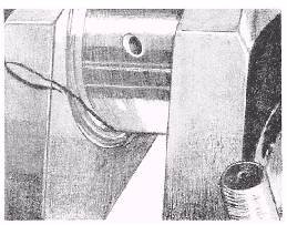
Figure 3-19.Cracked crank web. bearing. You can minimize the possibility of journal out-of-roundness by taking measures to pre-vent improper lubrication, journal bearing failure, overspeeding or overloading of the engine, excessive crankshaft deflection, and misalignment of parts. Crankshaft bending breakage (out-of-roundness) may also result from excessive crankshaft deflection. Excessive shaft deflection, caused by improper alignment between the driven unit and the engine, may result in a broken or bent shaft along with considerable other damage to bearings, connecting rods, and other parts. Ex-cessive crankshaft deflection may also be caused by overspeeding an engine. The amount of deflec-tion of a crankshaft may be determined by the use of a straight gage. The straight gage is merely a dial-reading inside micrometer used to measure the variation in the distance between adjacent crank webs where the engine shaft is barred over. When installing the gage, or indicator, between the webs of a crank throw, place the gage as far as possible from the axis of the crankpin. The ends of the indicator should rest in the prick-punch marks in the crank webs. If these marks are not present, you must make them so that the indicator may be placed in its correct position. Consult the manufacturers technical manual for the proper location of new marks. Readings are generally taken at the four crank positions: top dead center, inboard, near or at bottom dead center, and outboard. In some engines, it is possible to take readings at bottom dead center. In others, the connecting rod may interfere, making it necessary to take the reading as near as possible to bottom dead center without having the gage come in contact with the con-necting rod. The manufacturers technical manual for the specific engine provides information con-cerning the proper position of the crank when readings are to be taken. When the gage is in its lowest position, the dial will be upside down, necessitating the use of a mirror and flashlight to obtain a reading. Once the indicator has been placed in position for the first deflection reading, do NOT touch the gage until all four readings have been taken and recorded. Variations in the readings obtained at the four crank positions will indicate distortion of the crank. Distortion may be caused by several fac-tors, such as a bent crankshaft, worn bearings, or improper engine alignment. The maximum allowable deflection can be obtained from the manufacturers technical manual. If the deflec-tion exceeds the specified limit, take steps to deter-mine the cause of the distortion and to correct the trouble. Deflection readings are also employed to determine correct alignment between the engine and the generator, or between the engine and the coupling. When alignment is being determined, a set of deflection readings is usually taken at the crank nearest to the generator or the coupling. In aligning an engine and generator, it may be necessary to install new chocks between the generator and its base to bring the deflection within the allowable value. It may also be necessary to shift the generator horizontally to obtain proper alignment. When an engine and a coupling are to be aligned, the coupling must first be correctly aligned with the drive shaft; then, the engine must be properly aligned to the coupling, rather than the coupling aligned to the engine. |
||
|
||