Custom Search
|
|
 
|
||
|
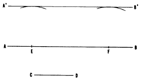
CHAPTER 4 DRAFTING: GEOMETRIC CONSTRUCTION Knowledge of the principles of geometric construction and its applications are essential to an Engineering Aid, As a draftsman, you must be able to "construct" or draw any of the various types of lines. In a line drawing, a line may be a straight line, a circle, an arc of a circle or a fillet, a circular curve, a noncircular curve, or a combination of these basic types of lines.You must also be able to construct line drawings at specified angles to each other, various plane figures, and other graphic repre-sentations consisting exclusively of lines. This chapter provides information that will aid you in drawing different types of geometric constructions.STRAIGHT LINES One method of drawing horizontal and vertical lines, perpendicular and parallel lines, and inclined lines is by using a straightedge (or a T square) with a triangle. Another practical method of constructing straight lines is by using a drafting compass.Figure 4-1 shows a method of drawing a line parallel to another line. Here, the line is to be drawn through given point C. To draw a line through C parallel to AB, place the needlepoint of the compass on any point D on AB, and strike arc CE. Shift the needlepoint to E, maintaining the same radius, and strike arc DF. Set a compass to a chord of arc CE, and lay off the chord DF from D, thus locating point F. A line drawn through F and C is parallel to AB.Figure 4-2 shows another method of drawing one line parallel to another, this one being used
Figure 4-1.-Drawing a line through a given point, parallel to another line.
Figure 4-2.-Drawing a parallel line at a given distance from another line.when the second line is to be drawn at a given distance from the first. To draw a line parallel to AB at a distance from AB equal to CD, set a compass to the length of CD, and, from any points E and F on AB, strike two arcs. A line AB drawn tangent to (barely touching) the arcs is parallel to AB, and located CD distance from AB.In the preceding chapter, you learned how to draw a line perpendicular to another by the use of a straightedge and a triangle. Two other methods of solving this problem are explained below.
Figure 4-3.-Dropping a perpendicular from a given point to a line. Figure 4-3 shows a method of dropping a perpendicular from a given point to a line, using a compass. To drop a perpendicular from point P to AB, set the needlepoint of the compass at P and strike an arc intersecting AB at C and D. With C and D as centers and any radius larger than one-half of CD, strike arcs intersecting at E. A line from P through E is perpendicular to AB.Figure 4-4 shows a method of erecting a perpendicular from a given point on a line. To erect a perpendicular from point P on AB, set a compass to any convenient radius, and, with P as a center, strike arcs intersecting AB at C and D. With C and D as centers and any radius larger than one-half of CD, strike arcs intersecting at E. A line from P through E is perpendicular to AB. |
||
|
||