Custom Search
|
|
 
|
||
|
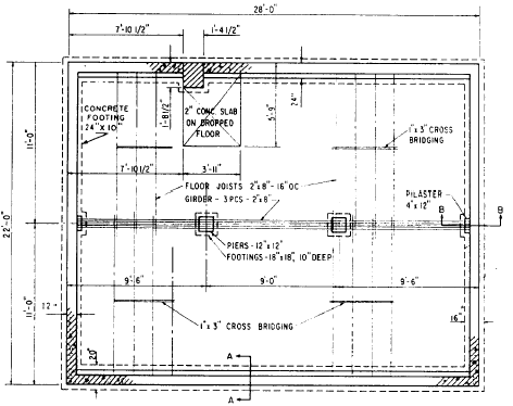
STRUCTURAL DRAWINGS STRUCTURAL DRAWINGS (sometimes identified with the designating letter S on their title blocks) consist of all the drawings that describe the structural members of the building and their relationship to each other. A set of structural drawings includes foundation plans and details, framing plans and details, wall sections, column and beam details, and other plans, sections, details, and schedules necessary to describe the structural components of the building or struc-ture.The general notes in the structural drawings should also include, when applicable, roof, floor, wind, seismic, and other loads, allowable soil pressure or pile bearing capacity, and allowable stresses of all material used in the design.Foundation Plan A FOUNDATION PLAN is a top view of the footings or foundation walls, showing their area and their location by distances between center lines and by distances from reference lines or boundary lines. Actually, it is a horizontal section view cut through the walls of the foundation showing beams, girders, piers or columns, and openings, along with dimensions and internal composition.The foundation plan is used primarily by the building crew who will construct the foundation of the proposed structure. In most SEABEE construction, foundations are built with concrete-masonry units and cast-in-place concrete. Figure 10-18 shows a plan view of a structure as it would look if projected into a horizontal plane that passes through the structure slightly below the level of the top of the foundation wall. The plan shows that the main foundation will consist of 12-in. concrete-masonry unit (CMU) walls measuring 28 ft lengthwise and 22 ft crosswise. In this plan, the CMU walls are identified by the standard symbol for concrete block. Ideally, a specific note should be added to call out the material.A girder running through the center of the building will be supported at the ends by two 4-by 12-in. concrete pilasters that will butt against the end foundation walls. Intermediate support for the girder will be provided by two 12-by 12-in. concrete piers, each supported on 18- by 18-in. spread footings, 10 in. deep. The dotted lines around the foundation walls indicate that these walls will also rest on spread footings.You need relative information about the total concept of the structure before you can draw the foundation plan. You must make a careful study of the materials and construction methods used, observe the type of foundation used, and analyze the relative position of the framing and the foundation wall or footing. You must also make reference to all of the applicable wall sections and typical sill details found in your texts and reference materials, such as the Architectural Graphics Standards before you start the foundation plan.In most drafting practices, it is customary to use the ground floor plan to develop the
Figure 10-18.-Example of a foundation plan. foundation plan because the floor plan readily offers the information you need for the foundation plan, such as the general shape of the building, openings, dimensions, and so forth. Some of the basic procedures in the proper development of a foundation plan are outlined below.1. Prepare and organize your drafting needs. Since the foundation plan is usually drawn at the same scale as the floor plan (1/4 in. = 1 ft), use the same sheet size and layout. A smaller scale (1/8 in. = 1 ft) may be used for the foundation plan when it is necessary to save space and provided that the amount of information given on this plan is limited. From an EAs point of view, drawing the foundation plan at the same scale as the floor plan is easier because you can use the floor plan to trace the outline and other features, thus saving time and effort. Ideally, centering the plan would provide more space for notes and details on footings.2. Lay out the drafting sheet lightly, beginning with the borders and title block. Tape the original, or preferably a print of the floor plan, under the sheet for the foundation plan if the same scale is being used. Draw the exterior outline of the foundation wall (usually the outside line of the exterior lines of the building), and also locate any retaining walls, steps, porches, and fireplaces. Again, be careful to notice what type of frame construction is used. The extent of using the floor plan in laying out the foundation plan varies among wood-frame, masonry, and steel-frame construction. Study these differences closely. Most often, dimensions are modified on the foundation plan, depending on the materials used. If the foundation is not drawn to the same scale as the floor plan, first determine the size of the foundation plan to be drawn, and lay it out on the sheet. Follow up by transferring all of the dimensions from the floor plan to the foundation plan. Locate other features accurately.3. Draw the inside wall of the foundation wall once the wall thickness is scaled and the outside foundation line is located. Along the wall, locate other features, such as access doors, vents, and pilasters. Also, draw the foundation for piers, columns, chimney, and retaining wall, if required.4. Lay out the footings. Check the standards for typical details on different types of footing and the minimum allowable footing size. Now, draw and note any additional structural information required. In wood-frame construction, the structural information for the first-floor construction is commonly shown on the foundation plan. If required, locate and lay in the supporting beam or girder and the size, spacing, and direction of floor joists.5. Lay out the dimensions. As in all of the EA work, be sure to double-check all of the dimensions to be certain they are correct and complete and that all of the features required are located in the drawing. Apply the principals and correct drafting techniques learned from chapter 3 of this book. Add all of the notes, materials, appropriate plan symbols, and other pertinent information required to complete the plan.6. Draw in the scale to the plan and the title of the drawing. Go over your foundation-plan checklist, and make sure the entire drawing is darkened in and labeled. |
||
|
||