Custom Search
|
|
 
|
||
|
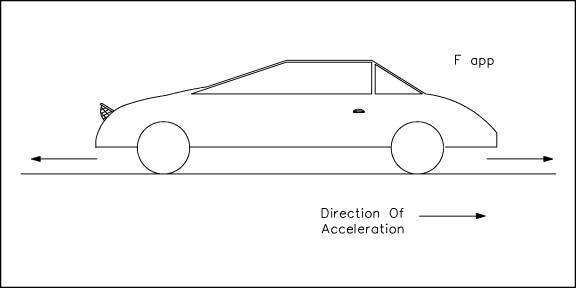
In constructing a free-body diagram the following steps are usually followed. Step 1.Determine which body or combination of bodies is to be isolated. The body chosen will usually involve one or more of the desired unknown quantities. Step 2.Next, isolate the body or combination of bodies chosen with a diagram that represents its complete external boundaries. Step 3.Represent all forces that act on the isolated body as applied by the removed contacting and attracting bodies in their proper positions in the diagram of the isolated body. Do not show the forces that the object exerts on anything else, since these forces do not affect the object itself. Step 4.Indicate the choice of coordinate axes directly on the diagram. Pertinent dimensions may also be represented for convenience. Note, however, that the free-body diagram serves the purpose of focusing accurate attention on the action of the external forces; therefore, the diagram should not be cluttered with excessive information. Force arrows should be clearly distinguished from other arrows to avoid confusion. For this purpose colored pencils may be used. When these steps are completed a correct free-body diagram will result, and the student can apply the appropriate equations to the diagram to find the proper solution. Example: The car in Figure 2 is being towed by a force of some magnitude. Construct a free-body diagram showing all the forces acting on the car.
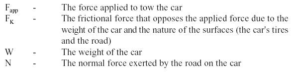
Figure 2 Car Solution: Following the steps to construct a free-body diagram (shown in Figure 3), the object (the car) is chosen and isolated. All the forces acting on the car are represented with proper coordinate axes. Those forces are:
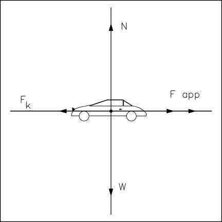
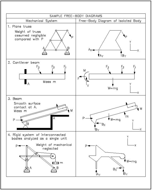
Figure 3 Free-Body Diagram The frictional force (FK) is a force that opposes the direction of motion. This force is explained in more detail in the chapter on types of forces. To solve this practical problem, the student would assign values for each force as determined by data given in the problem. After assigning a sign convention (e.g., + for forces upward and to the right, - for forces downward and to the left), the student would sum all forces to find the net force acting on the body. Using this net force information and appropriate equations, the student could solve for the requested unknowns. A variation would be to have the student find an unknown force acting on the body given sufficient information about the other forces acting on the body. The student will learn to solve specific examples using free-body diagrams in a later chapter. Some advanced free-body diagrams for various types of systems are shown in Figure 4.
Figure 4 Various Free-Body Diagrams |
 |
|
|
||