Custom Search
|
|
 
|
||
|
MECHANISMS. Grounding can reduce the interference in the five types of coupling mechanisms listed here. 1. Conductive Coupling. (Source and load wired together) It is sometimes practical to provide a separate return path for both the source and the load. If the system layout allows this, then conductive coupling cannot occur between these two, as is shown in Figures 10-2 and 10-3.
Figure 10-2. Arc currents through the process power supply return (existing ground) develop a voltage that appears in series with the process controls because they share that return.
Figure 10-3. It has been possible to install a separate return conductor for the power supply. The arc currents no longer appear in series with the process controls. There is no conductive coupling. 2. Capacitive Coupling. (High-impedance proximity coupling) The technique for increasing resistance to capacitive coupling among cables is to ground one end of the shield to produce the shortest, most direct shunt path back to the source of the coupled current as is shown in Figures 10-4 and 10-5. Caution: It is possible to inadvertently INCREASE coupling between source and load if the shield ground does not properly shunt the current coupled onto the shield. 3. Inductive Coupling. (Near-field, low-impedance loop-to-loop coupling) The technique for increasing resistance to magnetic coupling in shielded cables is to ground BOTH ends of the shield to an effective signal return ground as is shown in Figures 10-6 and 10-7. 4. System Signal Returns. Each installation will require individual analysis and treatment. A single ground poses no problem, but multiple grounds can result in a ground loop. These can upset the proper functioning of instruments. A signal isolator offers a way of overcoming the problem. 5. Instrumentation Grounding.' Equipment that is used to implement a control instrumentation strategy (see Figure 10-8) makes use of a common signal ground as a reference for analog signals. Any additional grounds that are introduced into the control circuit will almost certainly cause ground loops to occur. ' The information in this section and figures 10-8 and 10-9 are reprinted with permission from the September 1991 issue of EC&M magazine copyright (c) 1991 Intertec Publishing Corporation. All rights reserved.
A typical process instrumentation loop is shown in Figure 10-8. It is a DC system that operates at a specific voltage (24 volts in this case) to a master ground reference called a signal ground. The instrumentation signal varies within the range of 4-20 mA, depending upon the value of the variable (pressure, temperature, etc.) seen by the sensor. A precisely calibrated circuit takes this mA signal and converts it into a form that can be used by a process-control computer, PLC, dedicated instrument, or whatever controller that supervises the system. In this example, the mA signal is converted to a 1-5 V signal for a chart recorder. At 4 mA, the voltage measured by the recorder is 250 x.004 = 1 V. At 20 mA, the measured voltage is 5 V. Normally, the recorder scale is calibrated so the voltage reads directly in F, psi, etc. In order to minimize the danger of introducing ground loops into this complicated network of sensitive equipment, a dedicated instrumentation system ground bus is usually employed. This bus ultimately receives grounds from the signal common, the do power supply common, the cabinet ground, and the instrumentation ac power ground. The bus is tied to earth via the building ground and the plant ground grid. Figure 10-9 shows the typical way in which interconnection of these various grounds is accomplished. The cabinet ground is a safety ground that protects equipment and personnel from accidental shock hazards while providing a direct drain line for any static charges or electromagnetic interference
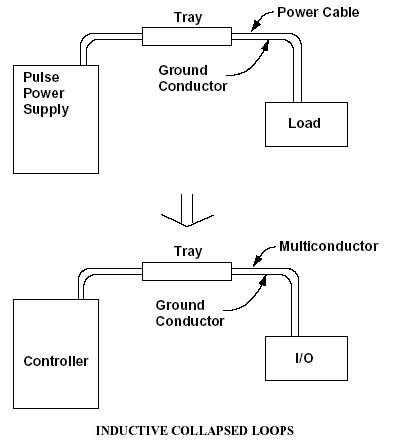
Figure 10-6. The pulse power supply, its cable, load, and return form a transmitting loop which couples into the loop formed by the controller, its multiconductor cabling, 1/0 and return. Note that in actual installations these loops can be very large and very close. (EMI) that may affect the cabinets. The cabinet ground remains separate from the do signal ground until it terminates at the master ground bus. Eliminating grounds is not feasible for some instruments, such as thermocouples and some analyzers, because they require a ground to obtain accurate measurements. Also, some instruments must be grounded to ensure personnel safety. When grounds cannot be eliminated, the solution to instrumentation ground loops lies in signal isolators. These devices break the galvanic path (dc continuity) between all grounds while allowing the analog signal to continue throughout the loop. An isolator also eliminates the noise of ac continuity (common-mode voltage).' ' Much of the information above came from the article which is titled "Causes and Cures of Instrumentation Ground Loops," by Pat Power, Moore Industries, Houston, TX.
Figure 10-7. Intentional returns have been installed for both the pulse power supply and the controller right in the trays for the cables. Both loops have been reduced to small cross sections, reducing inductive coupling. Any electromagnetic (far field) radiation being generated by the pulse power supply and its cabling will also be reduced.
|
||
|
||