
TM 5-5420-234-14&P
This task covers:
a.
Removal
b. Installation
c.
Follow-on Maintenance
INITIAL SETUP
Tools and Special Tools
Equipment Condition
Tool Kit, General Mechanic's: Automotive
Engine turned off (TM 9-2320-279-10)
(SC 5180-90-N26)
Wheels chocked (TM 9-2320-279-10)
Wrench, Combination, 1-1/8 in. (1172)
Materials/Parts
Special Environmental Conditions
Cable Ties (Item 8, Appendix E)
Cleanliness is extremely important when working
Lubricating Oil (Item 20, Appendix E)
on hydraulic equipment. Clean all parts before
Tags, Identification (as required) (Item 23,
disassembly and work in a clean work area.
Lockwasher (Item 73, Appendix K)
Lockwasher (10) (Item 90, Appendix K)
a. Removal.
WARNING
The LHS hydraulic system operates at oil pressures up to 3625 psi (24,994 kPa).
Never disconnect any hydraulic line or fitting without first dropping pressure to zero.
Failure to comply may result in serious injury to personnel.
NOTE
Tag and mark all hoses and tubes
prior to removal.
Cut cable ties as required.
Left and right side procedures are
the same. Left side is shown.
Cap and plug all hoses and tube
upon removal.
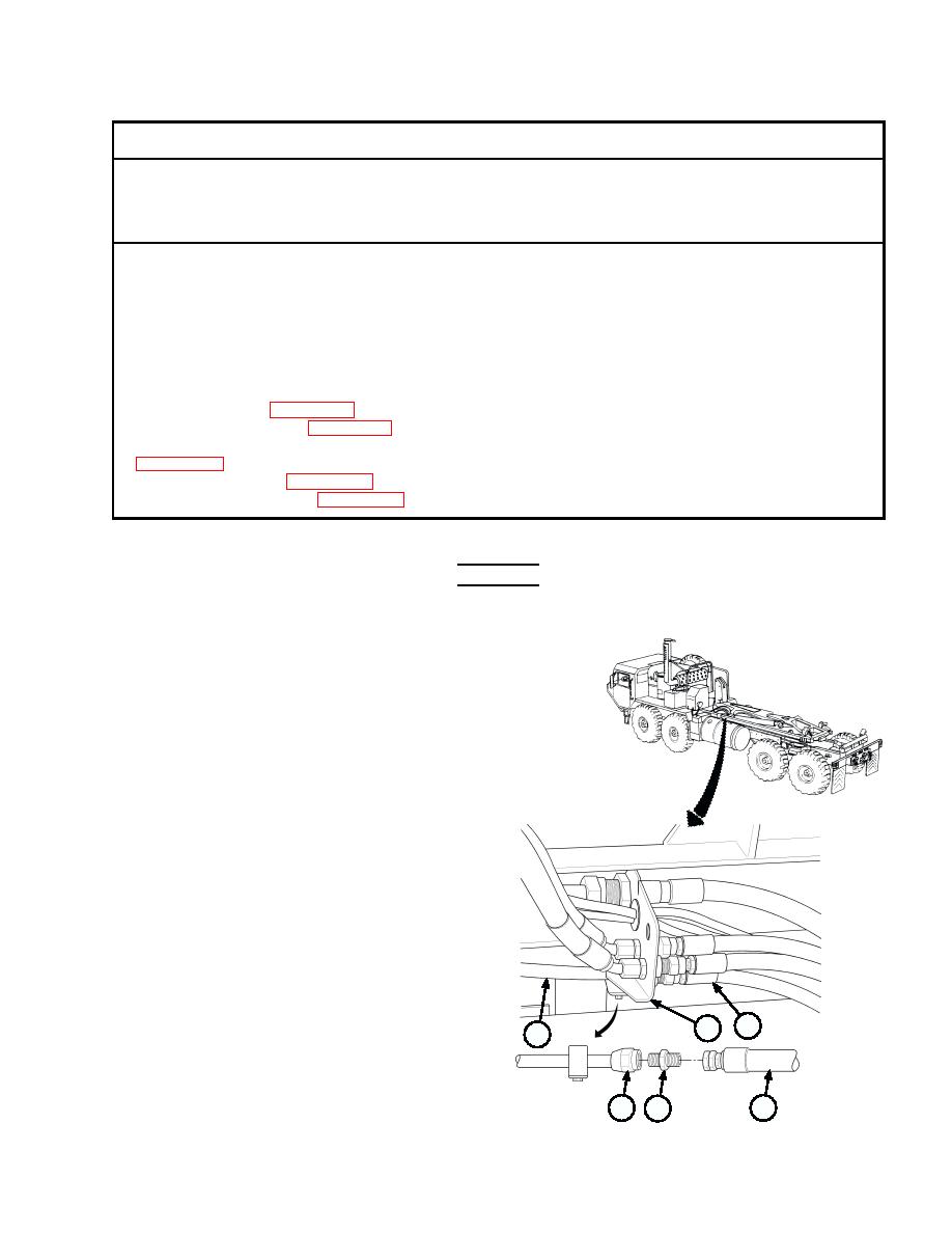
(1) Remove hose (1) from union (2) at front of
compression frame (3).
(2) Remove union (2) from tube (4).
1
3
4
4
1
2

