 |
|||
|
|
|||
|
|
|||
| ||||||||||
|
|
 TM 9-2320-364-34-1
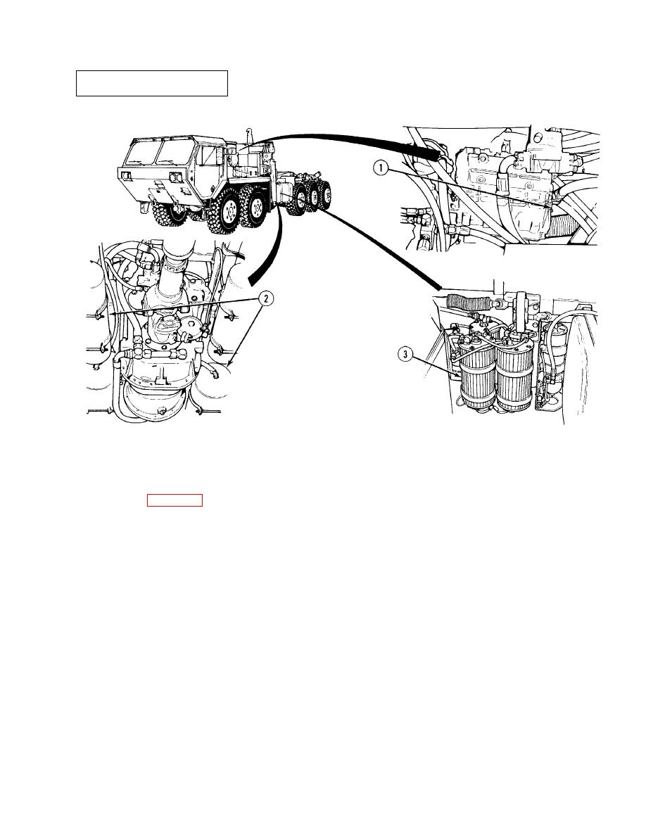
The air system (Figure 1-16) consists of an engine-driven air compressor (1) and five air reservoirs (2). The system
includes the necessary valves and air lines to control the truck's air operated devices. Pressurized air from the air
compressor is passed through the air dryer (3) to the reservoir. The air dryer removes dirt and moisture from the
pressurized air. Air from one reservoir goes to the brake treadle valve. This air passes to the rear brake chambers,
located on axles #3, #4, and #5, which control the axle rear service brake. Air pressure in this system is shown by the
red needle on the AIR PRESS gage. Air from another reservoir goes to the brake treadle valve. This air passes to the
front brake chambers, located on axles #1 and #2, which control the front axle service brakes. Air pressure in this
system is shown by the green needle on the AIR PRESS gage. The PARKING BRAKE valve applies or releases the
rear axle (parking) brakes. The reservoirs are interconnected in such a way that if one reservoir fails, air will be
supplied to release the rear axle (parking) brake from whichever reservoir is functioning. If air pressure falls below
60 to 70 psi (414 to 483 kPa) in either system, a buzzer will sound, the LOW AIR indicator will light and the rear axle
brakes will be applied.
|
|
Privacy Statement - Press Release - Copyright Information. - Contact Us |
