 |
|||
|
|
|||
|
Page Title:
BRAKES AND AIR SYSTEM-continued |
|
||
| ||||||||||
|
|
 TM 5-2420-224-34
Table 2-1. Troubleshooting (Cont)
Malfunction
Test or Inspection
Corrective Action
BRAKES AND AIR SYSTEM (CONT)
Step 2.
Check fluid regulating valve adjustment as follows:
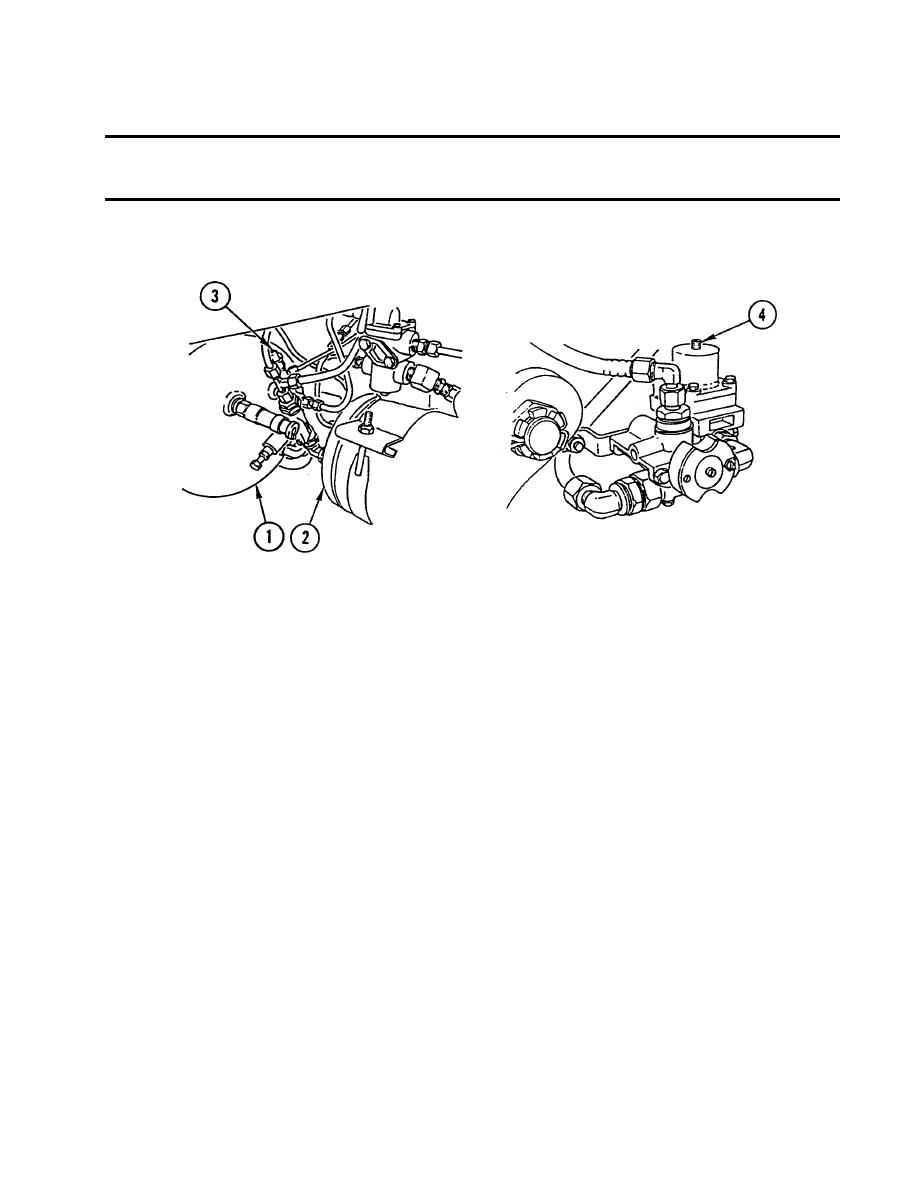
a. Relieve air pressure (TM 5-2420-224-20) completely from air tanks (1 and 2).
b. Attach 0-200 psi (0-14 bar) pressure gage to test connection (3).
NOTE
When fluid regulating valve reaches cut-out pressure, there will be an audible "pop".
c.
Start and run engine at idle until fluid regulating valve reaches cut-out pressure.
d. Compare pressure readings between 0-200 psi (0-14 bar) pressure gage and dual
brake gage. Both readings must be approximately 106 psi (7.3 bar).
If both readings are not approximately 106 psi (7.3 bar), turn fluid
regulating valve adjusting screw (4) 1/4-turn to right to increase
pressure, or 1/4-turn to left to decrease pressure. Relieve air
pressure (TM 5-2420-224-20) from air tanks (1 and 2) to approx-
imately 80 psi (5.5 bar) and repeat steps c and d until cut-out
pressure is approximately 106 psi (7.3 bar).
If correct cut-out pressure cannot be attained, replace fluid regulating
valve (TM 5-2420-224-20).
|
|
Privacy Statement - Press Release - Copyright Information. - Contact Us |
