 |
|||
|
|
|||
|
Page Title:
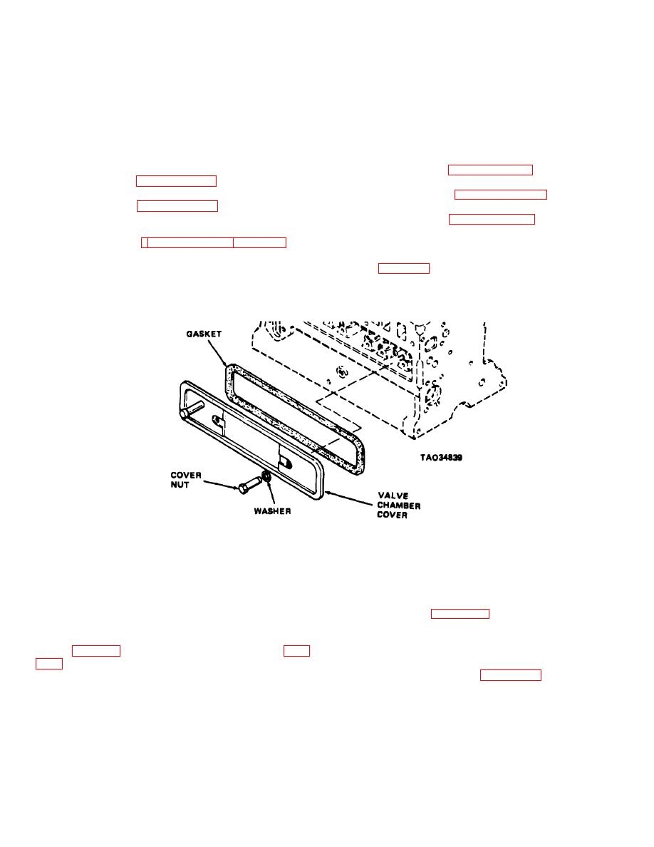
Figure 4-64. Valve chamber cover, removal and installation |
|
||
| ||||||||||
|
|
 TM 10-3930-630-12
4-83.
Engine Valves
(4) Tighten screws in successive stages to
ensure equal pressure over entire surface of cylinder
head and gasket. Hold tension on each screw for a few
seconds before releasing torque wrench.
mounted in the engine block and are operated by the
(5) At first pass apply approximately one-half
camshaft.
b. Adjustment. The valve tappet clearance may
of the recommended torque and then increase the
torque one-half each pass until recommended torque is
require adjustment.
obtained. Torque all screws to 70 to 75 pound-feet
(1) Open left side panel
(94.9 to 101.5 N-m).
(2) Refer to paragraph 4-57 and remove the
(6) Refer to paragraph 4-50 and install cooling
air cleaner.
temperature sending unit in cylinder head.
(3) Refer to paragraph 4-58 and remove
(7) Refer to paragraph 4-70 and install engine
carburetor and governor and associated linkage.
coolant outlet elbow and thermostat and connect coolant
(4) Refer to paragraph 4-50 and remove oil
bypass hose to cylinder head.
pressure and hourmeter actuator sending units.
(8) Refer to paragraphs 4-53 and 4-54 and
(5) Disconnect crankcase ventilation hose
instal spark plugs and distributor in cylinder head.
from valve chamber cover and remove valve chamber
(9) Close side panels and lower seat into
cover (fig. 4-64) and gasket from left side of engine
position.
beneath manifold.
Figure 4-64. Valve chamber cover, removal and installation
.
(6) Disconnect high tension wire from top of
(10) When timing pointer is in this position both
distributor. Clean area around spark plug and remove
valves on number one cylinder are closed on
spark plug from number one cylinder (spark plug closest
compression stroke
to coolant outlet elbow).
(11) Check valve tappet clearance with a feeler
(7) Refer to timing marks on flywheel or flex
gage as shown on figure 4-65.
plate.
(12) Clearance should be 0.012 inch (0.304
(a) To gain access to flex plate timing
mm) for intake valves and 0.020 inch (0.508 mm) for
exhaust valves.
marks (fig. 4-43) remove battery and battery box (para
(13) If clearances are not as specified use two
(b) Timing marks (fig. 443) at fuel pump
thin wrenches as shown in figure 4-66 to adjust valve
tappet clearance. Loosen the lock nut. Use the lower
location are accessible through hole in flywheel housing.
wrench to hold the tappet and the upper wrench to raise
(8) Place a thumb over the spark plug opening
or lower tappet adjusting screw.
and slowly crank engine until outward pressure can be
(14) Continue to raise or lower adjusting screw
felt against thumb. This pressure indicates number one
and checking with feeler gage until proper clearance is
piston is moving toward Top Dead Center of the
obtained.
compression stroke.
(15) Tighten lock nut when correct clearance is
(9) Continue cranking until timing pointer
obtained. Check clearance after tightening.
(fig.4-43) is in line with Dead Center mark on flywheel.
4-74
|
|
Privacy Statement - Press Release - Copyright Information. - Contact Us |
