 |
|||
|
|
|||
|
Page Title:
Section 3. OPERATING INSTRUCTIONS |
|
||
| ||||||||||
|
|
 SECTION 3
OPERATING INSTRUCTIONS
3-1.
GENERAL.
position of the switch turns off the headlight and taillight.
3-11.
PANIC BUTTON. The panic button is located
3-2.
This section describes, illustrates, locates, and
to the left of the light switch. Normal condition of the
furnishes the operator with sufficient information about
switch is the up position. The depressed position of the
the various controls and instruments to insure proper
switch disables the power circuit to the truck.
operation of the electric fork lift truck, Baker Model FTD-
040-EE.
3-12.
LIFT CONTROL LEVER. The lift control lever
is located on the cowl to the right of the operator's seat.
3-3.
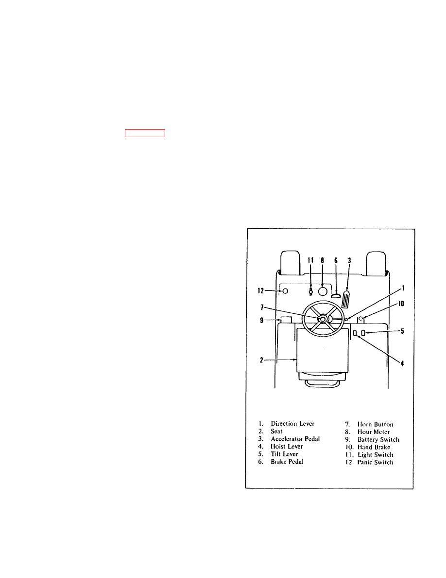
CONTROLS. (Refer to figure 3-1)
The rear position of the lever lifts the forks. The forward
position of the lever lowers the forks. The mid position
3-4.
BATTERY SWITCH.
When the battery
of the lever maintains the forks at any desired height.
connector is mated and the battery connector lever is
operated to the locked (down) position, the lever
3-13.
TILT CONTROL LEVER. The tilt control lever
operates the battery switch. The switch is in series with
is located directly to the right of the lift control lever.
the panic switch and seat switch to the master switch
The forward position of the tilt control lever tilts the forks
relay. This switch must be closed before the truck can
forward. The rear position of the lever tilts the forks
be operated.
backward. The mid-position of the lever maintains the
fork at any desired tilt angle.
3-5.
OPERATOR'S SEAT. As the operator places
his weight on the operator's seat, a seat switch is closed
to enable operation of the truck. Simultaneously, the
mechanical travel motor brake is released. As the
driver removes his weight from the seat, the motor
brake is engaged and the electrical circuit of the truck Is
disabled.
3-6.
HORN BUTTON. The horn button is located in
the center of the steering handwheel. Depressing the
button energizes the horn to sound an audible alarm.
3-7.
PARKING BRAKE LEVER. The parking brake
lever is located to the right of the operator's seat in front
of the cowl. The up position of the lever applies and
sets the mechanical brake which holds the truck in a
stationary position. Twisting the lever clockwise and
returning it to the down position releases the mechanical
brake.
3-8.
STEERING WHEEL.
The steering wheel
controls the direction of travel of the truck. Turning the
steering wheel clockwise moves the truck to the right;
turning the steering wheel counterclockwise moves the
truck to the left.
3-9.
ACCELERATOR PEDAL.
The accelerator
pedal is adjacent to the brake pedal, convenient to the
operator's right foot. The distance the accelerator pedal
is depressed determines the speed and acceleration
desired by the operator. Released pressure on the
pedal slows the speed of the truck.
3-10.
LIGHT SWITCH. The light switch is located on
Figure 3-1. Controls and Instruments.
the left side of the instrument panel. The ON position of
the switch turns on the headlight and taillight. The OFF
3-1
|
|
Privacy Statement - Press Release - Copyright Information. - Contact Us |
