
TM 11-5805-424-15/NAVELEX 0967-220-9010/TO 31W2-2G-41
(2) Adjustment.
(2) Connect the tagged leads disconnected in
a above to the terminal boards.
(a) Remove screw in top of oscillator
and oven assembly and insert thermocouple probe of
2-8. System Adjustments
temperature tester (Simpson Model 388-3L), NSN 6685-
00-975-4544, into oven through screw hole.
(b) Observe oven temperature until a
a. Bias.
stable reading is obtained. If not 75 C proceed to (c)
(1) Connect the oscilloscope between test
below.
point TP7 on the control shelf (fig. 2-3) and ground.
(c) Adjust OVEN TEMP ADJUST
(2) Adjust the oscilloscope to observe two
control R1 over a period of 10 minutes to obtain a 75C
crossover patterns.
indication on the temperature tester. Lock setting of R1
(3) Adjust the BIAS ADJ control for minimum
and apply a drop of glyptal varnish to shaft.
distortion (crossover points as near the center of the
(d) Remove probe from oven and
pattern as possible); then, disconnect the oscilloscope.
replace screw.
b. Delay Equalization (MX-7373/G, MX-7375/G,
f. Final Procedure.
MX-7383/G, and MX-7385/G).
(1) Disconnect the test equipment and the
shielded twisted pair signal cable connected in a above.
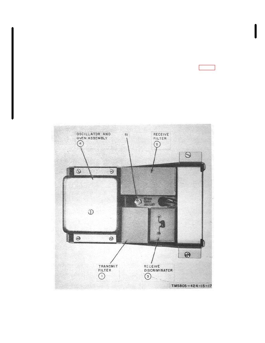
Figure 2 6. Plug-in module of Modem Subassembly MX-7372/G, MX-7374/G, MX-7376/G, MX-7377/G, MX-7378/G,
MX-7380/G MX-7381/G, MX-7382/G, MX 7384/G, or MX-7386/G.
Change 5
2-9

