TM 9-2520-272-34&P
4-11.
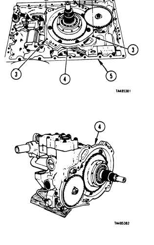
REMOVE BEVEL GEAR ASSEMBLY
(SHEET 2 OF 2)
1
2
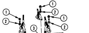
Using socket, attach three 3/8-16 x1-1/4 inch bolts (1)
and washers (2) until snug through sIing lugs and into
holes (3) in bevel gear assembly (4).
Using sling, lift bevel gear assembly
mission center housing (5).
CAUTION
When lowering bevel gear assembly onto
work table, be careful not to bend or break
tubes, Bent or broken tubes must be
replaced because:
• They may interfere with function of
bevel gear assembly.
• They may interfere with clearances
when bevel gear assembly is installed.
3 Using sling, carefully lower bevel gear assembly (4)
over work table. While lowering, turn assembly so
that it is supported by 2 x 4 x 16 inch wood blocks
4 Remove sling.
REPAIR: Refer to paragraphs 4-26 and 4-27 for
repair of bevel gear assembly.
FOLLOW-ON PROCEDURE: Install bevel gear
assembly. Refer to paragraph 4-12.
End of Task 1
Para. 4-11, Task 1
4 - 43
(4) out of trans-
|
|