
TM 5-3655-210-12
TS 024479
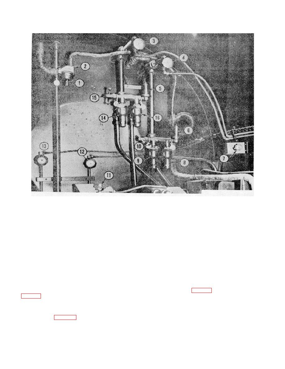
1.
Expansion valve adjusting screw
9.
Relief valve for carbon dioxide, storage
2.
Expansion valve
10.
Safety vent switching valve, storage
3.
low pressure gage line valve, conversion
11.
Safety relief valve, transfer pump
4.
Low pressure gage line valve, storage
12.
High pressure gage line valve, conversion
5.
Bleeder valve for carbon dioxide, conversion
13.
High pressure gage line valve, storage
6.
Bleeder valve for carbon dioxide, storage
14.
Relief valve for carbon dioxide, conversion
7.
Shutter control
15.
Safety vent switching valve, conversion
8.
Relief valve for carbon dioxide, storage
16.
Relief valve for carbon dioxide, conversion
Figure 2-1. Power compartment valves and controls
r. Toggle Switches (Momentary)..
line heaters in low temperatures to prevent the liquid
These two
carbon dioxide in the lines from solidifying, are located
toggle switches are located on the engine control panel.
on the gasoline engine control panel.
They are the gasoline engine START and STOP
p. Space Heater Switch. The space heater switch
switches (11 and 12, fig. 2-2). They are normally in the
(8, fig. 2-2) is located on the engine control panel. It is
OFF position and when moved to the ON position, will
a manually controlled switch controlling the heating of
spring back to OFF when pressure is released. These
the power compartment in low temperatures.
switches are used to start and stop the engine when on
q. Conversion Heater Switch. The conversion
manual control.
heater switch (9, fig. 2-2) is located on the engine
control panel.
It is a manually controlled switch
operating the conversion heater.
2-2

