
MWO 5-2330-360-23-1
10. INSTALLATION PROCEDURE M870A1 BRAKE MOD (BENDIX) (Continued).
i.
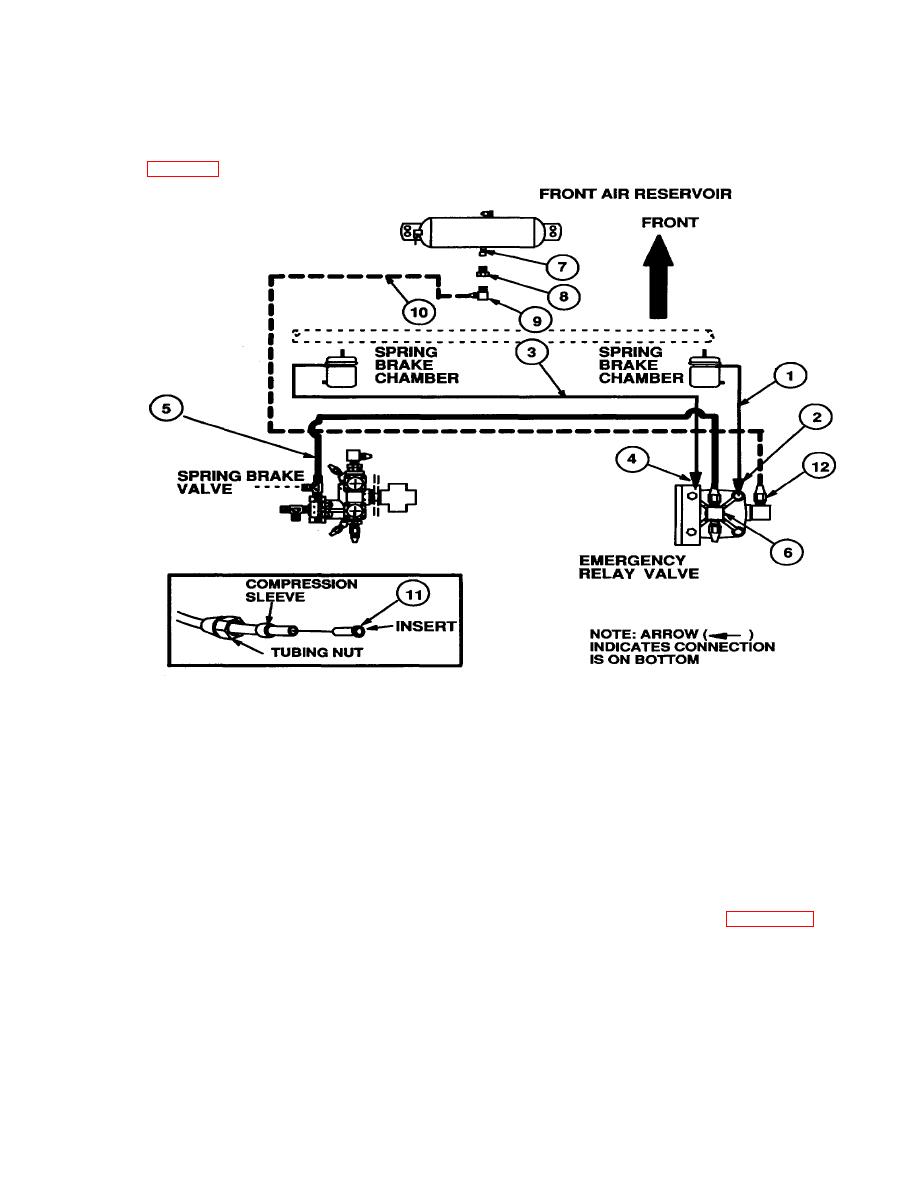
Connect Air Chamber Service Hoses and Air Lines.
Refer to Figure 28
Figure 28.
(1) Connect the front axle right air chamber service air hose (1). to the new relay valve right front delivery 45
degree elbow (2) adapter.
(2) Connect the front axle left air chamber service air hose (3), to the new relay valve left front delivery 45 degree
elbow (4) adapter.
(3) Connect the service air line (5) from the spring brake valve (3/8" tube), to the new relay valve tee (6), front
connection.
(4) Remove front air reservoir tank center plug at location (7). Dispose of plug as described in paragraph 8d..
(5) install reducing bushing (8), PN 234680. and elbow (9), PN 221825, in the front air reservoir center port at
location (7), facing the left (eight o'clock) position.
(6) Install new air line (10), PN 112473 (5/8" x 110" tube), and inserts (11), PN 247608, from the front air reservoir
tank elbow at location (7), rearward (through the left main frame crossmember opening), to the new relay valve elbow
(12).
29

