Custom Search
|
|
 
|
||
|
Testing Alarm-Indicating Devices Test alarm-indicating devices monthly with the monthly inspection. When convenient, the test may be combined with a fire drill. Test by operating the drill switch or the test switch at the control unit or by actuating an initiating device. If the test switch or an initiating device is used, notify the remote alarm headquarters because remote signal transmitters
Figure 7-18.\Audible signal appliances.
and other auxiliary features will be actuated by such a test. While there is an alarm condition, check all the indicating devices and note any that fail to operate properly. Audible devices should produce loud, clear, consistent tones, and coded system codes should be clearly recognizable. Visual devices should be bright and steady or pulsating, as intended. Test annunciator lamps by operating a "lamp test" switch if it is provided; otherwise, cause an alarm and a trouble condition on each zone. It is usually convenient to cause these conditions at the control unit initiating circuit terminals. When a single indicating' device fails to operate, it is usually defective. If a group of devices fails to operate, the fault is usually a defective circuit. TROUBLESHOOTING CIRCUIT FAULTS Because of the variations in equipment from manufacturer to manufacturer and the numerous types of circuits and devices in use, it is important to have the following reference materials available to personnel responsible for servicing: Wiring and Equipment Schematic Diagrams. Complete, accurate wiring diagrams of each type of device in use, of each circuit as installed, and equipment schematic diagrams. Manufacturers' Data Sheets. The descriptive information in manufacturers' data sheets on all equipment in use and
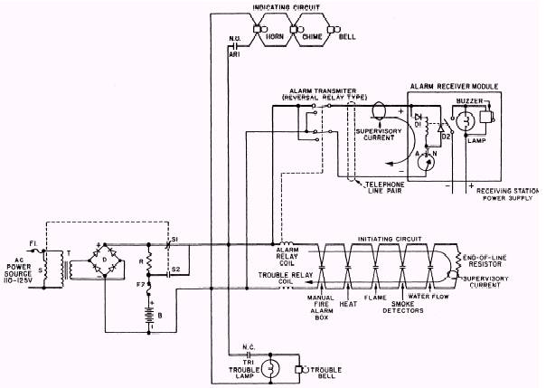
Figure 7-19.\Typical fire alarm system schematic diagram. manufacturers' instructions for any special testing and maintenance. System Revision Information. Information on all extensions or modifications to existing fire alarm systems. Tags. Identification of wires removed from terminals during repair or testing is essential to ensure accurate reconnection. Improperly connected wires may make a fire alarm device or circuit ineffective or may actually damage equipment. In general, detectors are returned to the manufacturer as a complete package for repair. However, control units and annunciators are large and interconnected with a number of other system components, and there should be some attempt at local repair before you ship the total unit to the manufacturer. Circuit faults may occur in the connection to the power source, in the alarm-initiating circuits, and in the alarm-indicating circuits. Procedures for locating the fault depend on which one of these is involved. Figure 7-19 represents a typical building fire alarm system. |
||
|
||