Custom Search
|
|
  |
|
|
TYPES OF APPLIANCES We will discuss various appliances that you will encounter throughout the Naval Construction Force (NCF). You may be called upon to install, troubleshoot, and repair all appliances mentioned here, plus others not covered within this chapter. Washing Machines The purpose of a washing machine is to clean clothes by forcing a mixture of water and a cleaning compound through the clothing regardless of how the machine is constructed. Washing machines can be classified in various ways, but generally they are divided into the agitator and tumbler types. Each type has advantages over the other and may have certain disadvantages, but each will give years of service if properly operated and maintained. COMPONENTS.- Before attempting any troubleshooting or repairs, you have to understand the components of the washer and their functions. Washers vary in construction, but their operating principles are similar. Electrical Supply.- Before connecting any washer to a power source, look at the motor nameplate or the manufacturer's manual to determine the correct electrical supply for the washer. Normally, a 120-volt, 60-cycle, 15-to 20-ampere circuit is required. Most machines come with a three-prong power cord that is to be inserted into a grounded duplex convenience outlet according to NEC(c) requirements. UNDER NO CIRCUMSTANCES SHOULD YOU REMOVE THE GROUND PRONG FROM THE PLUG. This prong is a ground that protects the user from electrical shock and possible electrocution. Timer.--The timer is the heart of the electrical system. It has a motor, an escapement, and multiple-circuit cam switches, all assembled into one unit. The timer (being a synchronous type of motor, like those in clocks) has a small pinion gear that drives the escapement. The escapement is a spring-powered mechanism that advances the time interval. The motor winds up a spring that unwinds abruptly to advance the camshaft the correct number of degrees. A ratchet mechanism in the escapement output gear permits the timer to be advanced manually. The camshaft opens and closes smaller switches in the multiple-circuit cam switch case. These switches control the operation of the washer. All electrical circuits come through the timer. The main ON/ OFF switch, operated by a push-pull action of the timer shaft, also is located within the timer housing. Motor.- The most essential component of a washer is the motor, which is usually a 1/ 3-horsepower, 120-volt unit. The motor supplies the power that operates the agitator, spins the tub, and operates the water pump. The motor is protected by a thermal overload protector connected in series with both the main and starting windings. The overload protector opens if the windings overheat. Some washers are equipped with two-speed motors and others have reversible motors. Belts from the motor to the transmission drive the agitator and the tub.
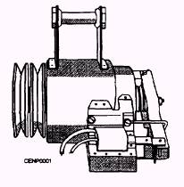
Figure 7-1 shows a typical washer
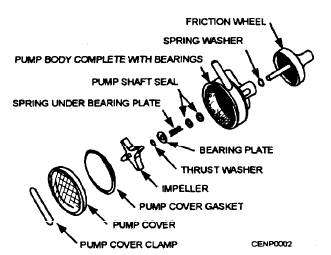
Figure 7-1.- Typical washer motor. motor with pulleys, mounting bracket, and high-speed solenoid. Pump.- The pump removes water from the tub after each cycle. Normally, the pump is located next to the motor and is engaged by the electrical solenoid. The solenoid engages the friction wheel of the pump (fig. 7-2) with the friction wheel on the motor, causing the shaft to turn the impeller and extract water from the tub. The discharge hose of the pump must be mounted above the water level of the tub, or the water will dram without the operation of the pump. In some cases, the pump is belt-driven and the solenoid tightens the belt to make the pump operate. One of the major causes of pump failure is foreign objects lodged in the pump impeller. To correct this situation, you remove the cover clamp (fig. 7-2) and the cover and remove the lodged item from the pump. Other causes are slippage between the friction wheels of the pump and motor and failure of the solenoid. Also, check for clogged hoses leading to and from the pump. Inlet Valves.- Water inlet valves equipped with two solenoids are called mixing valves. They have two water inlets: one hot and one cold. They actually mix hot and cold water. When the temperature control switch is set in the HOT position, the solenoid on the hot-water side of the valve is energized. That permits only hot water to enter the machine. Conversely, when the temperature control switch is set in the COLD position, the solenoid on the cold-water side of the valve is energized, and only cold water is permitted to enter. Positioning the switch in the WARM position energizes both solenoids, allowing hot and cold water to mix. When water fails to enter the machine naturally, check the water supply first. Then check the screen at the inlet valve. At the hose connection to the inlet valve, there is a fine screen: make sure it is free of any foreign
Figure 7-2.- Pump assembly. objects. Ensure that you have power to the inlet valve solenoid. Remember the electrical power must come through the water-level control switch, water-temperature selector switch, and timer. As a last resort, disassemble the valve and check for foreign objects. Also, ensure that the plunger inside the valve is free to operate; there must be at least 10 pounds of water pressure to overcome the spring pressure of the plunger in the solenoid valve.
|
 
|
|
|