Custom Search
|
|
  |
|
|
SERVICE ENTRANCE The service entrance serves to bring power from the service drop to the panelboard inside the building. One of the components of the service entrance is the conductors through which the current flows. The conductors may consist of individual wires run through a protective raceway, such as rigid metal conduit, electrical metallic tubing, or rigid nonmetallic conduit. The raceway provides the conductors with protection from both physical and weather damage. Power may also be brought into the building by means of service entrance cable. This cable does not need raceway protection unless it is likely to be physically damaged by abrasions or by being struck by passing equipment.
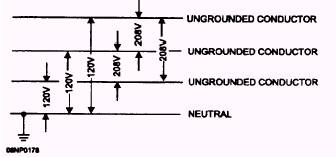
Figure 5-4.- Four-wire, three-phase system.
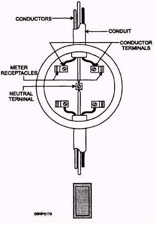
Figure 5-6.- Meter socket and wiring.
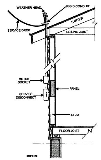
Figure 5-5.- Service mast service entrance. SERVICE DISCONNECTS A weather head, also called a service head, as shown in figure 5-5, is used with a raceway to provide an exit for the conductors from the raceway. The weather head is designed to prevent the entrance of rain into the raceway. The conductor holes in the service head are designed to reduce abrasion to the insulation. Power delivered to the building may need to be measured to determine how much power is used. When this measurement is necessary, a watt-hour meter socket (fig. 5-6) is installed in the service entrance circuit so that a wattmeter may be included to record power consumption. Article 230 of the NEC(c) covers the service conductors and equipment for control and protection of services and their installation requirements. The service entrance must provide a means of disconnecting the service entrance conductors from the interior building circuits. The service disconnecting means will be installed at a readily accessible location either outside of a building or structure, or inside nearest the point of entrance of the service conductors. A service disconnect, or main switch, can be used to turn off all interior power in case of a fire or other emergency conditions. A disconnect switch is also useful when work is to be performed on the panelboard or work is done on two or more circuits at the same time. Overcurrent protective devices are required for the service conductors in conjunction with the service disconnects. Several types of service entrance disconnects are permitted. One of these is in the form of a knife-blade switch with one, two, or three blades, as needed, to open the circuit. Figure 5-7 shows a two-pole knife-blade disconnect. As you can see, this switch has two fuses directly beneath the movable blades. Another type of disconnect is installed as a fuse block. The fuse block contains a fuse for each ungrounded conductor. Removal of the fuse block has the same effect as opening a switch to interrupt current flow. A third method of providing for service disconnect and overcurrent protection is the use of circuit breakers. These may be installed as a multiple assembly with a single-switch handle. The service disconnect must be permanently marked to identify it as a service disconnecting means. The grounded conductor is not normally attached to the disconnect switch, but when it is, the switch must be in the form of a circuit breaker, and all the ungrounded conductors must open simultaneously with the grounded conductor. Regardless of whether it is switched, the grounded conductor has to be fixed so it can be disconnected. A terminal or bus bar to which all grounded conductors can be attached by means of pressure connectors meets this requirement. The service entrance must be grounded to a low-resistance ground (refer to section 250 of the NEC(c)). Normally, a ground rod is driven into the ground for this
Figure 5-7.- Service entrance disconnect and overcurrent protection. purpose, but a metal underground water pipe in direct contact with the earth for 10 feet or more and electrically continuous to the points of connection of the grounding electrode conductor and the bonding conductors may be used. Another way is to use the nearest available effectively grounded structural metal member of the building for grounding. Once a suitable grounding electrode is identified, the grounded or neutral conductor must be attached to it. The grounding electrode conductor is installed as a continuous conductor from the neutral bus bar to the grounding electrode. Small grounding conductors are enclosed in a protective metal covering that should be electrically continuous from the panelboard cabinet to the grounding electrode. Metal raceways, meter sockets, panelboard cabinets, and the grounding electrode conductor enclosure must all be electrically bonded together and to the grounding electrode conductor so as to be electrically continuous. This arrangement results in all metal parts and enclosures in the service entrance and the grounded conductor being at the same potential electrically.
|
|
|
|