Custom Search
|
|
  |
|
|
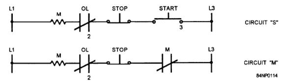
Schematic Diagram The schematic or elementary diagram (fig. 2-17) is a drawing that shows the electrical connections and functions of a specific circuit arrangement. It facilitates tracing the circuit and its functions without regard to the physical size, shape, or relative position of the component device or parts. The schematic diagram, like the connection diagram, makes use of symbols instead of pictures. Figure 2-17 shows, by a schematic diagram, the same motor control system shown in figures 2-14, 2-15, and 2-16. This diagram is laid out in a way that makes the operation of the components easy to understand. This type of schematic diagram with the components laid out in a line is sometimes called a one-line or single-line diagram. Most schematic diagrams are more complicated than 'the one shown in figure 2-17. The more complicated ones can be broken down into one-line diagrams, circuit by circuit. You can draw (or freehand sketch) your own one-line diagram by tracing only one circuit, component by component, through a multicircuit schematic, using the symbols in figure 2-6. Circuits "A" and "B" in figure 2-18 show only the control circuit from figure 2-16 laid out in one-line form. From these simple circuits, it is easy to see that as soon as the start button is pushed, the "M" coil (operating coil of the motor controller) will be energized. The operating coil is now held closed through the "M" contacts. Your own freehand sketches can help you understand other types of diagrams as well as the schematic. You may vary these sketches to suit your needs. You may draw a one-line diagram, using symbols, from a wiring diagram, an isometric diagram, or a connection diagram, as long as all the necessary details are there for you to convert to lines and symbols.
Figure 2-18.- One-line diagram of a motor control circuit.
|
|
|
|