Custom Search
|
|
  |
|
|
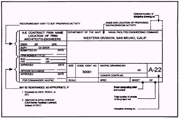
Title Block The requirements that determine what information must be included in a title block (fig. 2-1) vary. The title block, however, will contain the title of the drawing, the signature of the approving authority, the drawing number, the sheet number (when the drawing is one of a set of several sheets), and the number of sheets in the project set. The Naval Facility Engineering Command (NAVFACENGCOM) also requires the following information in title blocks: the name and location of the activity; the specifications and contract numbers (if any); the preparing activity, including the architect-engineer (A-E) firm, if applicable; and the surnames of the personnel concerned in the preparation of the drawings. The code identification number 80091 is to appear in the title block of all NAVFACENGCOM drawings as well as a sheet designation letter (I- Index, C- Civil, A- Architectural, S- Structural, M- Mechanical, P- Plumbing, E- Electrical, and W- Waterfront). Drawing Number All blueprints are identified by a drawing number that appears in a block in the lower right-hand comer of the title block. The drawing number is especially important, both for purposes of filing the blueprint and for locating the correct drawing when it is specified on another blueprint.
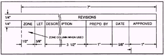
Figure 2-1.- Title block. Revision Block The revision block is usually located in the upper right-hand comer of the blueprint and is used for recording of changes (revisions) to the print. All revisions are noted in this block and are dated and identified by a letter and a brief description of the revision (fig. 2-2). Scale The graphic representation of the project is drawn to some proportion of the actual size of the project. One-eighth inch on such a drawing is equal to a foot of the actual size of the project. Although the original drawing is scaled accurately, your drawing will be a copy of that original and will not likely be the same size as the original drawing. The copy may have been reduced slightly. The paper size is also affected by temperature and humidity. The paper may stretch or shrink. Because of these factors, do not rely on measurements taken by laying a rule on the drawing. For example, do not assume that a number of units (as 1/ 8-inch increments) on the drawing is equal to that same number of feet on the project. This may or may
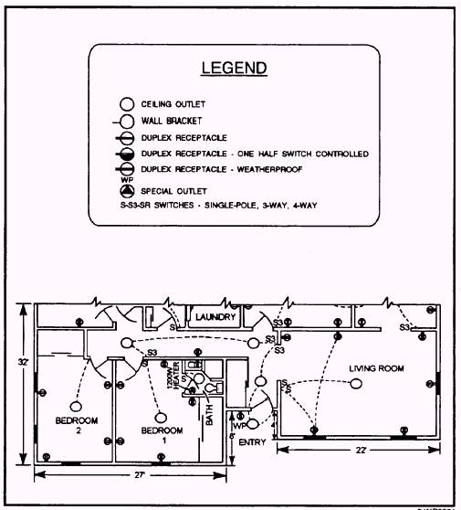
Figure 2-2.- Revision block. not be true. The assumption can result in expensive and time-consuming rework. Play it safe and read the dimensions shown on the drawing. Legend or Symbols The legend, if used, is generally placed in the upper right-hand comer of a blueprint below the revision block. The legend is used to explain or define a symbol or special mark placed on a blueprint. A symbol may have more than one meaning. It should be noted that all symbols used are not from a single standard. The important thing is that you understand the meaning of the symbols on the drawing on which you are working. The legend will give you that meaning. The legend in figure 2-3 shows the symbols and their meanings from the partial floor plan below it. Bill of Material On a blueprint, the bill of material block contains a list of the parts and material used on or required by the print concerned. The block identifies parts and materials by stock number or other appropriate number and also lists the quantity used or required. The bill of material often contains a list of standard parts, known as a parts list or schedule. Many commonly used items, such as machine bolts, screws, fittings, and valves, have been standardized by the
Figure 2-3.- A legend with partial floor plan. military. A bill of material for an electrical plan is shown in figure 2-4. SPECIFICATIONS Even well-drawn construction drawings cannot adequately reveal all the aspects of a construction project. There are many features that cannot be shown graphically. For instance, how can anybody show on a drawing the quality of workmanship required for the installation of electrical equipment or who is responsible for supplying the materials, except by extensive hand-lettered notes. The standard procedure then is to supplement construction drawings with written descriptions. These detailed written instructions, commonly called specifications (specs), define and limit the materials and fabrication according to the intent of the engineer or the designer. The specifications are an important part of the project because they eliminate possible misinterpretation and ensure positive control of the construction. There are many different types of specifications. A few of those common to the Naval Construction Force (NCF) will be discussed here.
|
|
|
|