Custom Search
|
|
  |
|
|
SPEED CONTROL OF SPLIT-PHASE AND CAPACITOR MOTORS Split-phase and capacitor motors are commonly used in floor and wall fans. Two-speed, split-phase, motors are normally made with two run windings and either one or two start windings, depending on the manufacturer. In a three-speed, split-phase motor, the speeds are obtained with only three windings: one running, one auxiliary, and one starting winding. For high speed, the running winding is connected across the line, and the starting winding is connected in series with the auxiliary winding across the line. For medium speed, the running winding is connected in series with half the auxiliary winding, and the starting winding is connected in series with the other half of the auxiliary winding. For low speed, the running and auxiliary windings are in series across the line, and the starting winding is connected across the line. Actually, a tap at the inside point of the auxiliary is brought out for medium speed. A centrifugal switch is connected in series with the starting winding. The capacitor motor used for two-speed floor fans is a permanent-split capacitor motor. This motor does not use a centrifugal switch. For three speeds, the auxiliary winding is tapped at the center point, and a lead is brought out for medium speed. This motor is similar to the three-speed, split-phase motor, except that the centrifugal switch is removed and a capacitor substituted. This motor is used extensively for blowers in air-conditioning systems. Split-phase motors used on wall fans are wound like the ordinary split-phase motor, but many do not have a centrifugal switch. A special type of autotransformer, located in the base of the fan, is used to change the speed and also to produce an out-of-phase current in the starting winding. The primary of the transformer is
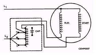
Figure 7-37.- Capacitor motor used for a wall fan.
Figure 7-38.- Three-phase motor. tapped for different speeds and is connected in series with the main winding. The starting winding is connected across the transformer secondary. Acapacitor motor for a wall fan (fig. 7-37) contains a capacitor of approximately 1 microfarad (f) in the starting-winding circuit. To increase the effective capacity and consequently the starting torque of this motor, connect the capacitor. across an autotransformer. The taps on the transformer permit a choice of various speeds.
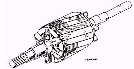
Figure 7-39.- Three-phase stator. SPEED CONTROL OF UNIVERSAL FAN MOTORS The universal fan motor has a resistance unit in the base to vary the speed. A lever that extends outside the base is used to insert the resistance in the circuit. CONSTRUCTION OF THREE-PHASE MOTORS Construction of a three-phase motor consists of three main parts: stator, rotor, and end bells. Its construction is similar to a split-phase motor, but the three-phase motor has no centrifugal switch (fig. 7-38). STATOR The stator, as shown in figure 7-39, consists of a frame and a laminated steel core, like that used in split-phase and repulsion motors, and a winding formed of individual coils, placed in slots. ROTOR The rotor may be a die-cast aluminum squirrel-cage type or a wound type. Both types contain a laminated core pressed onto a shaft. The squirrel-cage rotor (fig. 7-40) is like the rotor of a split-phase motor. The wound
Figure 7-40.- Squirrel-cage rotor.
Figure 7-41.- Three-phase wound rotor. rotor (fig. 7-41) has a winding on the core that is connected to three slip rings mounted on the shaft.
|
|
|
|