 |
||
|
|
||
| |||||||||||||||
|
|
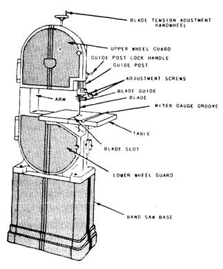
Band Saw Although the band saw (figure 3-3) is designed primarily for making curved cuts, it can also be used for straight cutting. Unlike the circular saw, the band saw is frequently used for freehand cutting. The band saw has two large wheels on which a continuous narrow saw blade, or band, turns, just as a belt is turned on pulleys. The lower wheel, located below the working table, is connected to the motor directly or by means of pulleys or gears and serves as the driver pulley. The upper wheel is the driven pulley. The saw blade is guided and kept in line by two sets of blade guides, one fixed set below the table and one set above with a vertical sliding adjustment. The alignment of the blade is adjusted by a mechanism on the backside of the upper wheel. Tensioning of the blade-tightening and loosening-is provided by another adjustment located just back of the upper wheel. Cutoff gauges and ripping fences are sometimes provided for use with band saws, but you'll do most of your work freehand with the table clear. With this type of saw, it is difficult to make accurate cuts when gauges or fences are used. The size of a band saw is designated by the diameter of the wheels. Common sizes are 14-, 16-, 18-, 20-, 30-, 36-, 42-, and 48-inch-diameter wheel machines. The 14-inch size is the smallest practical band saw. With the exception of capacity, all band
Figure 3-3.-Band saw. saws are much the same with regard to maintenance, operation, and adjustment. A rule of thumb used by many Seabees is that the width of the blade should be one-eighth the minimum radius to be cut. Therefore, if the piece on hand has a 4-inch radius, the operator should select a 1/2-inch blade. Don't construe this to mean that the minimum radius that can be cut is eight times the width of the blade; rather, the ratio indicates the practical limit for high-speed band saw work. Blades, or bands, for band saws are designated by points (tooth points per inch), thickness (gauge), and width. The required length of a blade is found by adding the circumference of one wheel to twice the distance between the wheel centers. Length can vary within a limit of twice the tension adjustment range. Band saw teeth are shaped like the teeth in a hand ripsaw blade, which means that their fronts are filed at 90 to the line of the saw. Reconditioning procedures are the same as those for a hand ripsaw, except that very narrow band saws with very small teeth must usually be set and sharpened by special machines. Observe the following safety precautions when operating a band saw: Keep your fingers away from the moving blade. Keep the table clear of stock and scraps so your work will not catch as you push it along. Keep the upper guide just above the work, not excessively high. Don't use cracked blades. If a blade develops a click as it passes through the work, the operator should shut off the power because the click is a danger signal that the blade is cracked and may be ready to break. After the saw blade has stopped moving, it should be replaced with one in proper condition. If the saw blade breaks, the operator should shut off the power immediately and not attempt to remove any part of the saw blade until the machine is completely stopped. If the work binds or pinches on the blade, the operator should never attempt to back the work away from the blade while the saw is in motion since this may break the blade. The operator should always see that the blade is working freely through the cut. A band saw should not be operated in a location where the temperature is below 45F. The blade may break from the coldness. Using a small saw blade for large work or forcing a wide saw on a small radius is bad practice. The saw blade should, in all cases, be as wide as the nature of the work will permit. Band saws should not be stopped by thrusting a piece of wood against the cutting edge or side of the band saw blade immediately after the power has been shut off; doing so may cause the blade to break. Band saws with 36-inch-wheel diameters and larger should have a hand or foot brake. Particular care should be taken when sharpening or brazing a band saw blade to ensure the blade is not overheated and the brazed joints are thoroughly united and finished to the same thickness as the rest of the blade. It is recommended that all band saw blades be butt welded where possible; this method is much superior to the old style of brazing. Drill Press Figure 3-4 shows a drill press. (The numbers in the figure correspond to those in the following text.) The drill press is an electrically operated power machine that was originally designed as a metal-working tool; as such, its use would be limited in the average woodworking shop. However, accessories, such as a router bit or shaper heads, jigs, and special techniques, now make it a versatile woodworking tool as well. The motor (10) is mounted to a bracket at the rear of the head assembly (1) and designed to permit V-belt changing for desired spindle speed without removing the motor from its mounting bracket. Four spindle speeds are obtained by locating the V-belt on any one of the four steps of the spindle-driven and motor-driven pulleys. The belt tensioning rod (16) keeps proper tension on the belt so it doesn't slip. The controls of all drill presses are similar. The terms "right" and "left" are relative to the operator's position standing in front of and facing the drill press. "Forward" applies to movement toward the operator. "Rearward" applies to movement away from the operator. The on/off switch (11) is located in the front of the drill press for easy access. The spindle and quill feed handles (2) radiate from the spindle and quill pinion feed (3) hub, which is located on the lower right-front side of the head assembly (1). Pulling forward and down on any one of the three spindle and quill feed handles, which point upward at the time, moves the spindle and quill assembly downward. Release the feed handle (2) and the spindle and quill assembly return to the retracted or upper position by spring action. The quill lock handle (4) is located at the lower left-front side of the head assembly. Turn the quill lock handle clockwise to lock the quill at a desired operating position. Release the quill by turning the quill lock handle counterclockwise. However, in most cases, the quill lock handle will be in the released position. The head lock handle (5) is located at the left-rear side of the head assembly. Turn the head leek handle clockwise to lock the head assembly at a desired vertical height on the bench column. Turn the head lock handle counterclockwise to release the head assembly. When operating the drill press, you must ensure that the head lock handle is tight at all times. The head support collar handle (6) is located at the right side of the head support collar and below the head assembly. The handle locks the head support collar, which secures the head vertically on the bench column, and prevents the head from dropping when the head lock handle is released. Turn the head support collar lock handle clockwise to lock the support to the bench column and counterclockwise to
Figure 3-4.-Drill press. release the support. When operating the drill press, ensure that the head support collar lock handle is tight at all times. As you face the drill press, the tilting table lock handle is located at the right-rear side of the tilting table bracket. The lockpin secures the table at a horizontal or 45 angle. This allows you to move the table to the side, out of the way for long pieces of wood. The table support collar (8) allows you to raise or lower the table. Turn the tilting table lock handle counterclockwise to release the tilting table bracket so it can be moved up and down or around the bench column. Lock the tilting table assembly at the desired height by turning the lock handle clockwise. When operating the drill press, ensure that the tilting table lock handle is tight at all times. The adjustable locknut (14) is located on the depth gauge rod (17). The purpose of the adjustable locknut is to regulate depth drilling. Turn the adjustable locknut clockwise to decrease the downward travel of the spindle. The locknut must be secured against the depth pointer (13) when operating the drill press. The depth of the hole is shown on the depth scale (15). Observe the following safety precautions when operating a drill press: Make sure that the drill is properly secured in the chuck (12) and that the chuck key (9) is removed before starting the drill press. Make sure your material is properly secured. Operate the feed handle with a slow, steady pressure to make sure you don't break the drill bit or cause the V-belt to slip. Make sure all locking handles are tight and that the V-belt is not slipping. Make sure the electric cord is securely connected and in good shape. Make sure you are not wearing hanging or loose clothing. Listen for any sounds that may be signs of trouble. After you have finished operating the drill press, make sure the area is clean. |
|
Privacy Statement - Press Release - Copyright Information. - Contact Us - Support Integrated Publishing |