 |
||
|
|
||
| |||||||||||||||
|
|
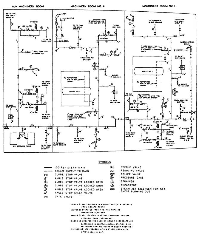
SHIPBOARD PIPING PRINTS There are various types of shipboard piping systems. Figure 5-13 shows a section of a piping diagram for a heavy cruiser. Note that the drawing uses the standard symbols shown in figure 5-9, and that it includes a symbol list. Some small piping diagrams do not include a symbol list; therefore, you must be familiar with the standard symbols to interpret these diagrams. Standard symbols are generally not used in drawings of shipboard piping systems found in operation and maintenance manuals. Each fitting in those systems may be drawn in detail (pictorially), as shown in figure 5-14, or a block diagram arrangement (fig. 5-15) may be used. HYDRAULIC PRINTS The Navy has increased its use of hydraulic systems, tools, and machines in recent years. Hydraulic systems are used on aircraft and aboard ship to activate weapons, navigational equipment, and remote controls of numerous mechanical devices. Shore stations use hydraulically operated maintenance and repair shop equipment. Hydraulic systems are also used in construction, automotive, and weight-handling equipment. Basic hydraulic principles are discussed in the basic training course Fluid Power, NAVEDTRA 12064. To help you distinguish one hydraulic line from another, the draftsman designates each line according
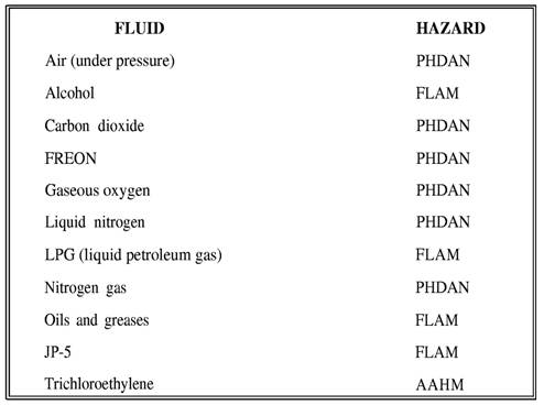
Figure 5-12.-Hazards associated with various fluids.
Figure 5-13.-A section of an auxiliary steam system piping diagram.
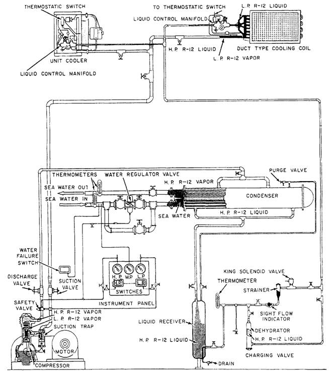
Figure 5-14.-Shipboard refrigerant circulating air-conditioning system.
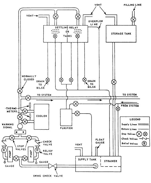
Figure 5-15.-Shipboard forced-lubrication system.
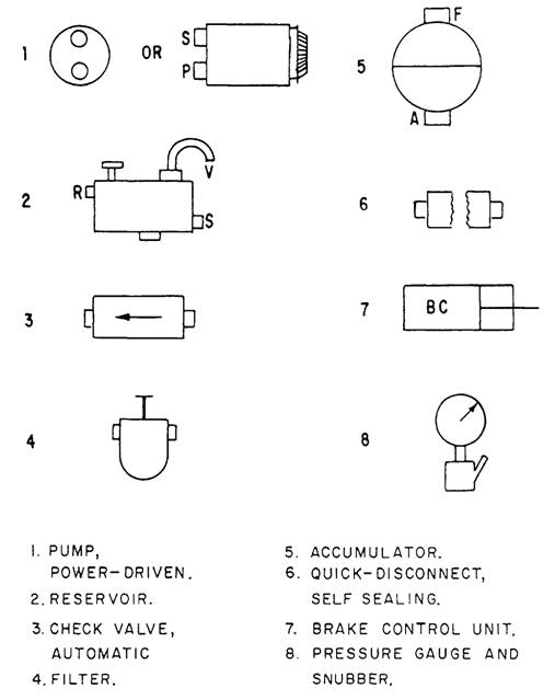
to its function within the system. In general, hydraulic lines are designated as follows: SUPPLY LINES-These lines carry fluid from the reservoir to the pumps. They may be called suction lines. PRESSURE LINES-These lines carry only pressure. They lead from the pumps to a pressure manifold, and from the pressure manifold to the various selector valves. Or, they may lead directly from the pump to the selector valve. OPERATING LINES-These lines alternately carry pressure to, and return fluid from, an actuating unit. They also may be called working lines. Each line is identified according to its specific function. RETURN LINES-These lines return fluid from any portion of the system to a reservoir. VENT LINES-These lines carry excess fluid overboard or into another receptacle. MIL-STD-17B, part II, lists symbols that are used on hydraulic diagrams. Figure 5-16 shows the basic outline of each symbol. In the actual hydraulic diagrams the basic symbols are often improved, showing a cutaway section of the unit.
Figure 5-16.-Basic types of hydraulic symbols.
Figure 5-17 shows that the lines on the hydraulic diagram are identified as to purpose and the arrows point the direction of flow. Figure 5-18 and appendix II contain additional symbols and conventions used on aircraft hydraulic and pneumatic systems and in fluid power diagrams. |
|
Privacy Statement - Press Release - Copyright Information. - Contact Us - Support Integrated Publishing |