 |
||
|
|
||
| |||||||||||||||
|
|
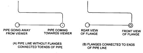
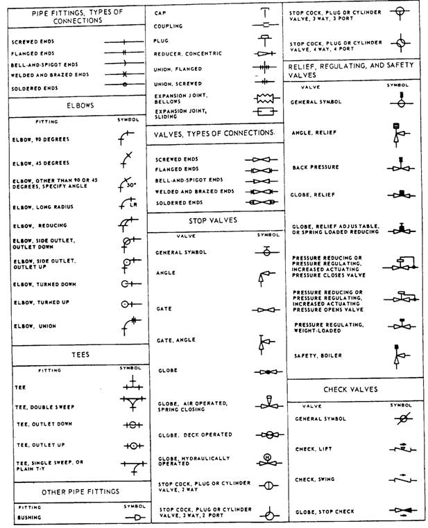
FITTINGS If standard symbols for fittings like tees, elbows, crossings, and so forth are not shown on a drawing, they are represented by a continuous line. The circular symbol for a tee or elbow may be used when it is necessary to show the piping coming toward or moving away from the viewer. Figure 5-8, views A and B, show circular symbols for a connection with and without flanges. Symbols and Markings MIL-STD-1713, part I, lists mechanical symbols used on piping prints other than those for aeronautical, aerospacecraft, and spacecraft, which are listed in MIL-STD-1713, part II. Figure 5-9 shows common symbols from MIL-STD-1713, part 1. Note that the symbols may show types of connections
Figure 5-8.-Indicating ends of pipe and fittings.
Figure 5-9.-Symbols used in engineering plans and diagrams.
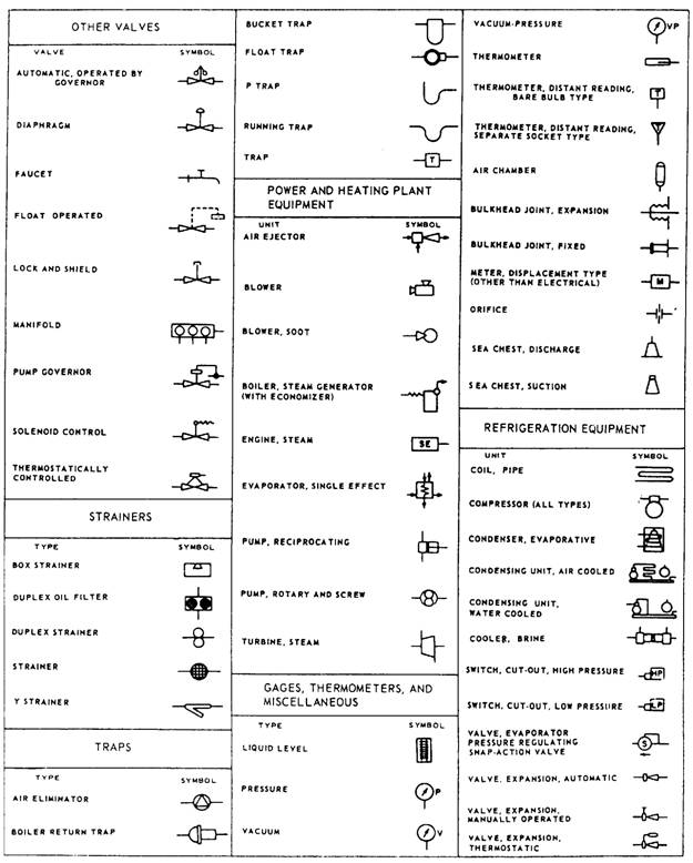
Figure 5-9.-Symbols used in engineering plans and diagram-Continued.
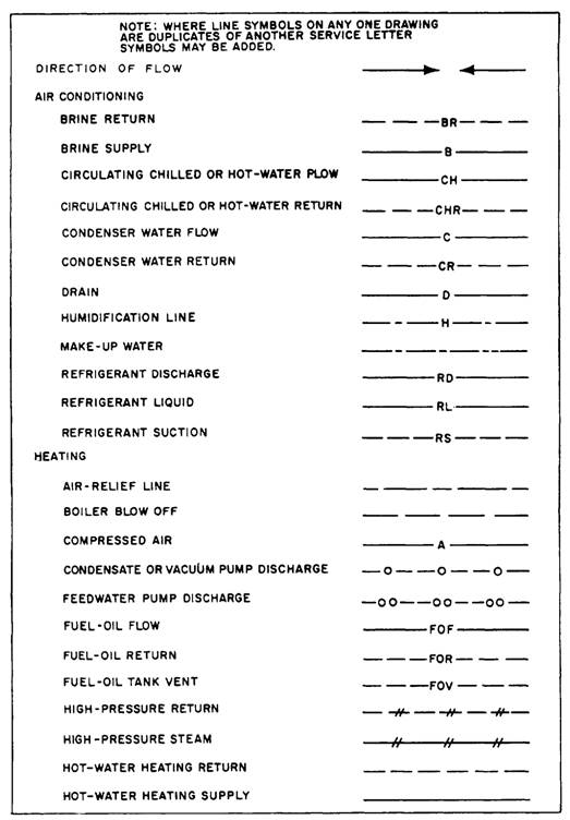
Figure 5-10.-Pipe line symbols. (screwed, flanged, welded, and so forth) as well as fittings, valves, gauges, and items of equipment. When an item is not covered in the standards, the responsible activity designs a suitable symbol and explains it in a note. Figure 5-10 shows some of the common piping symbols used in piping prints. When a print shows more than one piping system of the same kind, additional letters are added to the symbols to differentiate between the systems. MIL-STD-101C established the color code used to identify piping carrying hazardous fluids. It applies to all piping installations in naval industrial plants and shore stations where color coding is used. While all valve wheels on hazardous fluid piping must be color coded, the piping itself is optional. The following
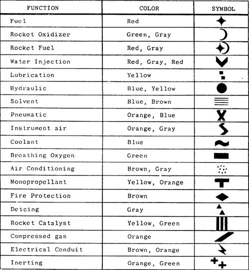
Fluid lines in aircraft are marked according to MIL-STD-1247C, Markings, Functions, and Designations of Hoses, Piping, and Tube Lines for Aircraft, Missiles, and Space Systems. Figure 5-11 lists the types of aircraft fluid lines with the color code and symbol for each type. Aircraft fluid lines are also
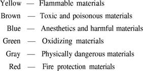
Figure 5-11.-Aircraft fluid line color code and symbols. marked with an arrow to show direction of flow and hazard marking, as you will see later in this chapter. The following paragraphs contain markings for the four general classes of hazards, and figure 5-12 shows examples of the hazards in each class. FLAM This marking identifies all materials ordinarily known as flammable or combustible. TOXIC - This marking identifies materials that are extremely hazardous to life or health. AAHM This marking identifies anesthetics and harmful materials. These include all materials that produce anesthetic vapors. They also include those that do not normally produce dangerous fumes or vapors, but are hazardous to life and property. PHDAN This marking identifies a line that carries material that is not dangerous in itself, but is asphyxiating in confined areas. These materials are generally handled in a dangerous physical state of pressure or temperature. |
|
Privacy Statement - Press Release - Copyright Information. - Contact Us - Support Integrated Publishing |