 |
||
|
|
||
| |||||||||||||||
|
|
ISOMETRIC PROJECTION Isometric projection is the most frequently used type of axonometric projection, which is a method used to show an object in all three dimensions in a single view. Axonometric projection is a form of orthographic projection in which the projectors are always perpendicular to the plane of projection. However, the object itself, rather than the projectors, are at an angle to the plane of projection. Figure 3-6 shows a cube projected by isometric projection. The cube is angled so that all of its surfaces make the same angle with the plane of projection. As a result, the length of each of the edges shown in the projection is somewhat shorter than the actual length of the edge on the object itself. This reduction is called foreshortening. Since all of the surfaces make the angle with the plane of projection, the edges foreshorten in the same ratio. Therefore, one scale can be used for the entire layout; hence, the term isometric which literally means the same scale. VIEWS The following pages will help you understand the types of views commonly used in blueprints. MULTIVIEW DRAWINGS The complexity of the shape of a drawing governs the number of views needed to project the drawing. Complex drawings normally have six views: both ends, front, top, rear, and bottom. However, most drawings are less complex and are shown in three views. We will explain both in the following paragraphs. Figure 3-7 shows an object placed in a transparent box hinged at the edges. With the outlines scribed on each surface and the box opened and laid flat as shown in views A and C, the result is a six-view orthographic
Figure 3-6.-Isometric projection.
Figure 3-7.-Third-angle orthographic projection.
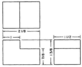
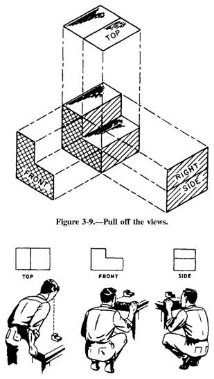
projection. The rear plane is hinged to the right side plane, but it could hinge to either of the side planes or to the top or bottom plane. View B shows that the projections on the sides of the box are the views you will see by looking straight at the object through each side. Most drawings will be shown in three views, but occasionally you will see two-view drawings, particularly those of cylindrical objects. A three-view orthographic projection drawing shows the front, top, and right sides of an object. Refer to figure 3-7, view C, and note the position of each of the six sides. If you eliminate the rear, bottom, and left sides, the drawing becomes a conventional 3-view drawing showing only the front, top, and right sides. Study the arrangement of the three-view drawing in figure 3-8. The views are always in the positions shown. The front view is always the starting point and the other two views are projected from it. You may use any view as your front view as long as you place it in the lower-left position in the three-view. This front view was selected because it shows the most characteristic feature of the object, the notch. The right side or end view is always projected to the right of the front view. Note that all horizontal outlines of the front view are extended horizontally to make up the side view. The top view is always projected directly above the front view and the vertical outlines of the front view are extended vertically to the top view. After you study each view of the object, you can see it as it is shown in the center of figure 3-9. To clarify the three-view drawing further, think of the object as immovable (fig. 3-10), and visualize yourself moving around it. This will help you relate the blueprint views to the physical appearance of the object.
Figure 3-8.-A three-view orthographic projection.
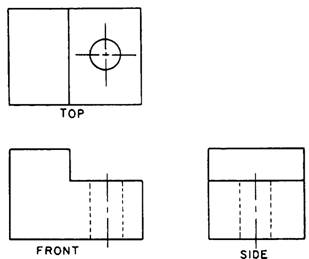
Figure 3-10.-Compare the orthographic views with the model. Now study the three-view drawing shown in figure 3-11. It is similar to that shown in figure 3-8 with one exception; the object in figure 3-11 has a hole drilled in its notched portion. The hole is visible in the top view, but not in the front and side views. Therefore, hidden (dotted) lines are used in the front and side views to show the exact location of the walls of the hole. The three-view drawing shown in figure 3-11 introduces two symbols that are not shown in figure 3-8 but are described in chapter 2. They are a hidden line that shows lines you normally can't see on the object, and a center line that gives the location of the exact center of the drilled hole. The shape and size of the object are the same.
Figure 3-11.-A three-view drawing. |
|
Privacy Statement - Press Release - Copyright Information. - Contact Us - Support Integrated Publishing |