 |
||
|
|
||
| |||||||||||||||
|
|
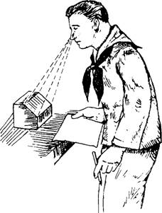
A perspective drawing is the most used method of presentation used in technical illustrations in the commercial and architectural fields. The drawn objects appear proportionately smaller with distance, as they do when you look at the real object (fig. 3-12). It is difficult to draw, and since the drawings are drawn in diminishing proportion to the edges represented, they cannot be used to manufacture an object. Other views are used to make objects and we will discus them in the following paragraphs. SPECIAL VIEWS In many complex objects it is often difficult to show true size and shapes orthographically. Therefore, the draftsmen must use other views to give engineers and craftsmen a clear picture of the object to be constructed. Among these are a number of special views, some of which we will discuss in the following paragraphs.
Figure 3-12.-The perspective. Auxiliary Views Auxiliary views are often necessary to show the true shape and length of inclined surfaces, or other features that are not parallel to the principal planes of projection. Look directly at the front view of figure 3-13. Notice the inclined surface. Now look at the right side and top views. The inclined surface appears foreshortened, not its true shape or size. In this case, the draftsman will use an auxiliary view to show the true shape and size of the inclined face of the object. It is drawn by looking perpendicular to the inclined surface. Figure 3-14 shows the principle of the auxiliary view. Look back to figure 3-10, which shows an immovable object being viewed from the front, top, and side. Find the three orthographic views, and compare them
Figure 3-13.-Auxiliary view arrangement.
Figure 3-14.-Auxiliary projection principle. with figure 3-15 together with the other information. It should clearly explain the reading of the auxiliary view. Figure 3-16 shows a side by side comparison of orthographic and auxiliary views. View A shows a foreshortened orthographic view of an inclined or slanted surface whose true size and shape are unclear. View B uses an auxiliary projection to show the true size and shape. The projection of the auxiliary view is made by the observer moving around an immovable object, and the views are projected perpendicular to the lines of sight. Remember, the object has not been moved; only the position of the viewer has changed. Section Views Section views give a clearer view of the interior or hidden features of an object that you normally cannot see clearly in other views. A section view is made by visually cutting away a part of an object to show the shape and construction at the cutting plane.
Figure 3-15.-Viewing an inclined surface, auxiliary view.
Figure 3-16.-Comparison of orthographic and auxiliary projections. Notice the cutting plane line AA in the front view shown in figure 3-17, view A. It shows where the imaginary cut has been made. In view B, the isometric view helps you visualize the cutting plane. The arrows point in the direction in which you are to look at the sectional view. View C is another front view showing how the object would look if it were cut in half. In view D, the orthographic section view of section A-A is placed on the drawing instead of the confusing front view in view A. Notice how much easier it is to read and understand. When sectional views are drawn, the part that is cut by the cutting plane is marked with diagonal (or crosshatched), parallel section lines. When two or more parts are shown in one view, each part is sectioned or crosshatched with a different slant. Section views are necessary for a clear understanding of complicated parts. On simple drawings, a section view may serve the purpose of additional views.
Figure 3-17.-Action of a cutting plane.
Section A-A in view D is known as a full section because the object is cut completely through. OFFSET SECTION.-In this type of section, the cutting plane changes direction backward and forward (zig-zag) to pass through features that are important to show. The offset cutting plane in figure 3-18 is positioned so that the hole on the right side will be shown in section. The sectional view is the front view, and the top view shows the offset cutting plane line. HALF SECTION.-This type of section is shown in figure 3-19. It is used when an object is symmetrical in both outside and inside details. One-half of the object is sectioned; the other half is shown as a standard view. The object shown in figure 3-19 is cylindrical and cut into two equal parts. Those parts are then divided equally to give you four quarters. Now remove a quarter. This is what the cutting plane has done in the pictorial view; a quarter of the cylinder has been re
Figure 3-18.-Offset section.
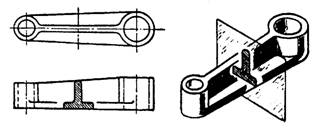
Figure 3-19.-Half section. moved so you can look inside. If the cutting plane had extended along the diameter of the cylinder, you would have been looking at a full section. The cutting plane in this drawing extends the distance of the radius, or only half the distance of a full section, and is called a half section. The arrow has been inserted to show your line of sight. What you see from that point is drawn as a half section in the orthographic view. The width of the orthographic view represents the diameter of the circle. One radius is shown as a half section, the other as an external view. REVOLVED SECTION.-This type of section is used to eliminate the need to draw extra views of rolled shapes, ribs, and similar forms. It is really a drawing within a drawing, and it clearly describes the object's shape at a certain cross section. In figure 3-20, the draftsman has revolved the section view of the rib so you can look at it head on. Because of this revolving feature, this kind of section is called a revolved section. REMOVED SECTION.-This type of section is used to illustrate particular parts of an object. It is drawn like the revolved section, except it is placed at one side to bring out important details (fig. 3-21). It is
Figure 3-20.-Revolved section.
Figure 3-21.-Removed section. often drawn to a larger scale than the view of the object from which it is removed. BROKEN-OUT SECTION.-The inner structure of a small area may be shown by peeling back or removing the outside surface. The inside of a
Figure 3-22.-Broken-out section through a counterbored hole.
Figure 3-23.-Aligned section. counterbored hole is better illustrated in figure 3-22 because of the broken-out section, which makes it possible for you to look inside. ALIGNED SECTION. Figure 3-23 shows an aligned section. Look at the cutting-plane line AA on the front view of the handwheel. When a true sectional view might be misleading, parts such as ribs or spokes are drawn as if they are rotated into or out of the cutting plane. Notice that the spokes in section A-A are not sectioned. If they were, the first impression might be that the wheel had a solid web rather than spokes. Exploded View This is another type of view that is helpful and easy to read. The exploded view (fig. 3-24) is used to show the relative location of parts, and it is particularly helpful when you must assemble complex objects. Notice how parts are spaced out in line to show clearly each part's relationship to the other parts. |
|
Privacy Statement - Press Release - Copyright Information. - Contact Us - Support Integrated Publishing |