Custom Search
|
|
  |
|
|
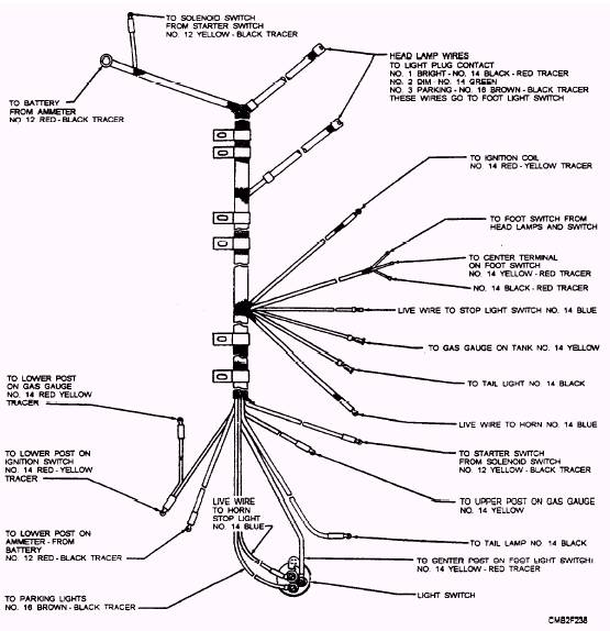
Wiring assemblies consist of wires and cables of definitely prescribed length, assembled together to form a subassembly that will interconnect specific electrical components and/ or equipment. The two basic types of wiring assemblies are as follows: The CABLE ASSEMBLY consists of a stranded conductor with insulation or a combination of insulated conductors enclosed in a covering or jacket from end to end. Terminating connections seal around the outer jacket so that the inner conductors are isolated completely from the environment. Cable assemblies may have two or more ends. WIRING HARNESS assemblies (fig. 2-86) serve two purposes. They prevent chafing and loosening of terminals and connections caused by vibration and road shock while keeping the wires in a neat condition away from moving parts of the vehicle. Wiring harnesses contain two or more individual conductors laid parallel or twisted together and wrapped with binding material, such as tape, lacing cord, and wire ties. The binding materials do not isolate the conductors from the environment completely, and conductor terminations may or may not be sealed. Wiring harnesses also may have two or more ends. WIRING IDENTIFICATION
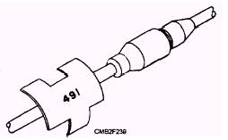
Figure 2-86.- A typical wiring harness. Wiring found on tactical equipment (M-series) has no color. All the wires used on these vehicles are black. Small metal tags (fig. 2-87), stamped with numbers or
Figure 2-87.- Metal tag wire identification. codes, are used to identify the wiring illustrated by diagrams in the technical manuals. These tags are securely fastened near the end of individual wires. WIRING DIAGRAMS Often you will find ELECTRICAL SYMBOLS used in wiring diagrams to simulate individual components. Figure 2-89 shows some of the symbols you may encounter when tracing individual circuits in a wiring diagram. |
 
|
|
|