Custom Search
|
|
  |
|
|
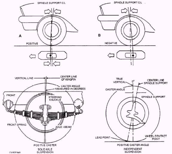
Steering geometry is the term manufacturers use to describe steering and wheel alignment. The six fundamental angles or specifications that are required for a proper wheel alignment are as follows: Caster Steering Axis Inclination Caster Caster controls where the tire touches the road in relation to an imaginary center line drawn through the spindle support. It is NOT a tire wear angle. The basic purposes for caster are as follows: To aid directional control of the vehicle To offset road crown pull (steering wheel pull caused by the slope of the road surface) Caster is measured in DEGREES starting at the true vertical (plumb line). Manufacturers give specifications for caster as a specific number of degrees positive or negative. Typically, specifications list more positive caster for vehicles with power steering and more negative caster for vehicles with manual steering (to ease steering effort). Depending upon the vehicle manufacturer and type of suspension,
Figure 8-48.- Caster angle. Negative caster (fig. 8-48) tilts the top of the steering knuckle toward the front of the vehicle. With negative caster, the wheels will be easier to turn. However, the wheels tend to swivel and follow imperfections in the road surface. Positive caster (fig. 8-48) tilts the top of the steering knuckle towards the rear of the vehicle. Positive caster helps keep the wheels of the vehicle traveling in astraight line. When you turn the wheels, it lifts the vehicle. Since this takes extra turning effort. the wheels resist turning and try to return to the straight-ahead position. Camber To aid steering by placing vehicle weight on the inner end of the spindle To prevent tire wear on the outer or inner tread To load the larger inner wheel bearing Positive and negative camber (fig. 8-49) is measured from the true vertical (plumb line). If the wheel is aligned with the plumb line, camber is zero. With positive camber, the tops of the wheels tilt outward when viewed from the front, With negative camber, the tops of the wheels tilt inward when viewed from the front. Most vehicle manufacturers suggest a slight positive camber setting from a 1/ 4 to a 1/ 2 degree. Suspension wear and above normal curb weight caused by several passengers or heavy loads tend to increase negative camber. Positive camber counteracts this. Toe TOE-IN is produced when the front wheels are closer together in the front than at the rear, when measured at the hub height. Toe-in causes the wheels to point inward at the front.
Figure 8-49.- Camber angle.
TOE-OUT results when the front of the wheels are farther apart than the rear. Toe-out causes the front of the wheels to point away from each other. The type of drive (rear or front wheel) determines the toe settings. Rear-wheel drive vehicles are usually set to have TOE-IN at the front wheels. This design is due to as a result of the front wheels moving outward while driving, resulting in toe-out. By adjusting the wheels for a slight toe-in (1/ 16 to 1/ 4 in.), the wheels and tires will roll straight ahead when driving. Front-wheel drive vehicles require different adjustment for toe. This is due to the front wheels driving the vehicle and are pushed forward by engine torque. This makes the wheel toe-in or point inward while driving. To compensate for this. front-wheel drive vehicles have the front wheels adjusted for a slight toe-out (1/ 16 inch). This adjustment will give the front end a zero toe setting. as the vehicle travels down the road. |
|
|
|