Custom Search
|
|
  |
|
|
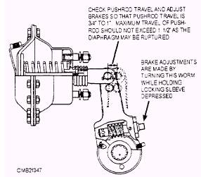
The brake chamber (fig. 7-45) converts the energy of the compressed air into mechanical force to operate the brakes. When the brake pedal is actuated, air under pressure enters the brake chamber behind the diaphragm and forces the pushrod out against the return spring force. Because the yoke on the end of the pushrod is connected to the slack adjuster, this movement rotates the slack adjuster. brake camshaft, and cam to apply the brakes. When the pedal is released, air is forced from the brake chamber by the brake shoe return spring acting on the linkage. After the shoes reach the fully released position, the return springs acting on the diaphragm causes it to return to its original position in the chamber. When performing maintenance of the brake system, check the brake chamber alignment to avoid binding action. Check the pushrod travel periodically, and when necessary'. adjust the brakes so that pushrod travel is as short as possible without the brakes dragging. The pushrod length should be adjusted so that the angle between the center line of the slack adjuster and the brake chamber pushrod is 90 degrees when the pushrod is extended to the center of its working stroke. SLACK ADJUSTERS The entire slack adjuster rotates as a lever with the brake camshaft, as the brakes are applied or released. Turning the adjusting screw makes the brake adjustments necessary to maintain proper slack adjuster arm travel (shoe and drum clearance). This action rotates the worm gear, camshaft, and cam. expanding the brake shoes so that the slack caused by brake lining wear is eliminated and the slack adjuster arm travel is returned to the correct setting. The movement of the cam forces the brake shoes against the brake drum. Friction of the brake lining against the drum stops the turning movement of the wheel. When the brakes are released, the brake shoe return spring pulls the shoes back to a DISENGAGED position. BRAKE VALVES
Figure 7-45.- Brake chamber.
Treadle valve (brake valve) Treadle Valve Maintenance of the treadle valve consists of periodic lubrication of the hinge and roller. Should the valve malfunction, it can be disassembled and cleaned. After cleaning, the internal parts should be lubricated with Vaseline before reassembly. This prevents moisture in the air system from causing corrosion and freezing of the valve. If cleaning does not remedy the malfunction, the valve must be replaced. Trailer Control Valve |
|
|
|