Custom Search
|
|
  |
|
|
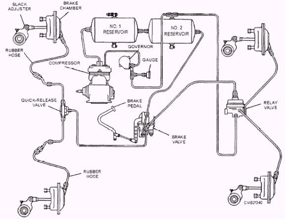
The COMPRESSOR is driven from the engine crankshaft or one of the auxiliary shafts. The three common methods of driving the compressor from the engine are gear, belt, and chain. The compressor may be lubricated from the engine crankcase or self-lubricating. Cooling may be either by air or liquid
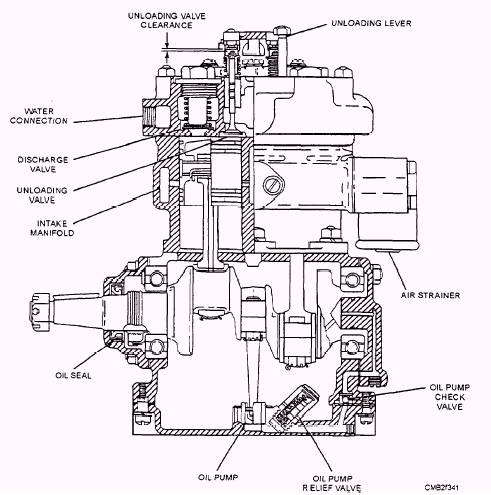
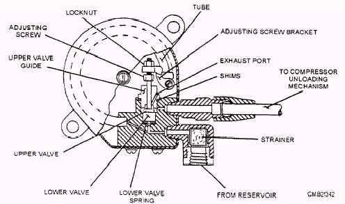
Figure 7-39.- Typical air brake system. from the engine. Compressors, having a displacement of approximately 7 cubic feet per minute (cfm), have two cylinders, while those with a displacement of 12 cfm have three cylinders. The reciprocal air compressor (fig. 7-40) operates continuously while the engine is running, but the governor controls the actual compression. The operation of the compressor is as follows: The partial vacuum created on the piston downstroke draws air through the air strainer and intake ports into the cylinder. As the piston starts its upstroke. the intake ports are closed off, and the air trapped in the cylinder is compressed. The pressure developed lifts the discharge valve, and the compressed air is discharged to the reservoirs. As the piston starts its downstroke. pressure is relieved, closing the discharge valve. The purpose of the compressor GOVERNOR is to maintain the air pressure in the reservoir between the maximum pressure desired (100 to 110 psi) and the minimum pressure required automatically for safe operation (80 to 85 psi) by controlling the compressor unloading mechanism. In the type O-1 governor (fig. 7-41) air pressure from the reservoir enters the governor through the strainer and is always present below the tower valve and in the spring tube. As the air pressure increases, the tube tends to straighten out and decrease pressure on the valve. When the reservoir air pressure reaches the cutout setting of the governor (100 to 110 psi), the spring load of the tube on the tower valve has been reduced enough to permit air pressure to raise the tower valve off its seat. This movement of the lower valve raises the upper valve to its seat, which closes the exhaust port. Air then flows up through the small hole in the lower
Figure 7-40.- Typical two-cylinder reciprocal air compressor.
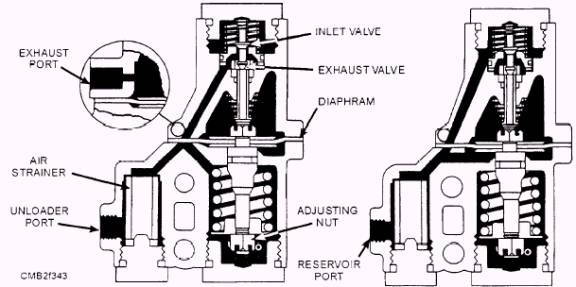
valve and out the upper connection to the unloader assembly located in the compressor cylinder head. When the unloader valves open, the compression of air is stopped. When reservoir pressure is reduced to the cut-in setting of the compressor governor (80 to 85 psi), the governor tube again exerts sufficient spring pressure on the valve mechanism to depress and close the lower valve and open the upper valve, thereby shutting off and exhausting the air from the compressor unloading mechanism and compression is resumed. The pressure range and setting should be checked periodically using an air gauge known to be accurate. Pressure range may be changed in the type O-1 governor by adding shims beneath the upper valve guide to decrease the range, or removing shims to increase the range. Pressure settings may be changed, if necessary, by turning the adjusting screw to the left to increase the setting or to the right to decrease the setting. The strainer should be removed periodically and cleaned. Check the governor periodically for excessive leakage in both the cut-in and cutout positions. If the governor fails to operate properly, it should be repaired or replaced. In the type D governor (fig. 7-42) when the reservoir pressure reaches the cut-out setting (100 to 110 psi), the governor diaphragm is subjected to sufficient air pressure to overcome the spring loading. This action allows the valve mechanism to move up, permitting the exhaust stem to close the exhaust valve and to open the inlet valve. Reservoir pressure then passes through the governor to operate the compressor unloading mechanism. stopping further compression of the air compressor. When the reservoir pressure is reduced to the cut-in setting (80 to 85 psi). the spring loading within the governor overcomes the air pressure under the diaphragm. The valve mechanism is actuated, closing the inlet valve and opening the exhaust valve, thereby shutting off and exhausting the air from the compressor unloading mechanism and compression is resumed. Pressure range and setting should be checked periodically, using an accurate air gauge. The pressure range (pressure differential) between loading and unloading of the type D governor is a function of the design of the unit and should not be changed. The designed range for this governor is approximately 20 percent of the cutout pressure setting. The pressure settings of the type D governor may be adjusted by turning the adjusting nut clockwise to increase or counterclockwise to decrease the settings. Both strainers should be removed periodically and cleaned or replaced. The governor should periodically be checked for leakage at the exhaust port in both the cut-in and cutout positions. If the governor fails to operate properly, it should be repaired or replaced.
Figure 7-42.- Type D governor. When the reservoir air pressure reaches the maximum setting of the governor, air under pressure is allowed by the governor to pass into a cavity below an unloading diaphragm. This air pressure lifts one end of the unloading lever, which pivots on its pin and forces the unloading valves off their seats. With the unloading valves off their seats, the unloading cavity forms a passage between the cylinders above the pistons. Air then passes back and forth through the cavity between the cylinders and compression is stopped. A drop in air pressure below the minimum setting of the governor causes it to release the air pressure from beneath the unloading diaphragm, allowing the unloading valves to return to their seats resuming compression. |
|
|
|