Custom Search
|
|
  |
|
|
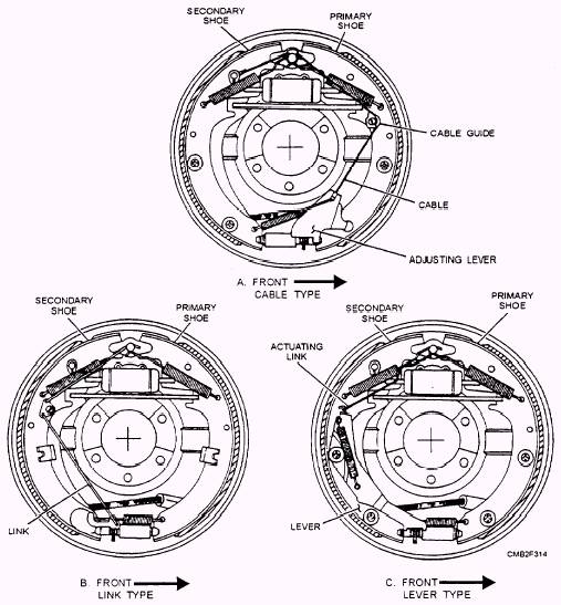
Many vehicles use a star wheel (screw) type brake shoe adjusting mechanism. This type consists of a star wheel (adjusting screw assembly), adjuster lever, adjuster spring, and an adjusting mechanism. The adjustment system may grouped as follows (fig. 7-13): Cable type- The cable type self-adjusting system (fig. 7-13) uses a braided steel cable and the expanding action of both brake shoes to accomplish the self-adjusting action in forward and reverse directions. A one-piece cable is attached to the adjusting lever and passes through a cable guide on the primary shoe. The
Figure 7-13.- Self-adjusting mechanisms. cable then is passed up and over the anchor and attached to the secondary shoe. Operation is as follows: 1. Brakes are applied and the shoes expand and contact the drum. 2. The primary shoe self-energizes, and, through servo action, applies the secondary shoe. 3. The heel of the secondary shoe is lodged against the anchor pin. 4. The movement of the primary shoe tightens the cable by shifting the cable guide outward and in the direction of rotation. 5. The cable then moves the adjusting lever upward. If enough shoe-to-drum clearance is available, the adjusting lever will engage the next tooth on the star wheel. The brake shoes retract and the cable slackens, as the brakes are released. The return spring then helps force the adjusting lever downward, rotating the star wheel, which expands the brake shoes. In the reverse direction, the toe of the primary shoe is forced against the anchor, and the secondary shoe moves around to tighten the adjusting cable. The adjusting process is then completed. Link type- The link type self-adjusting system (fig. 7-13) uses solid linkage rods to connect the adjusting lever to the stationary anchor point. The two linkage rods, connected together by a bell crank that pivots on the secondary brake shoe, operate the adjuster. One rod attaches to the anchor point and the bell crank, while the other rod connects the bell crank and the adjusting lever. In this configuration. the self-adjuster works only in reverse direction. As the vehicle is backing up and the brakes are applied, the adjusting process is as follows: 1. The secondary, shoe moves away from the anchor because of the self-energizing action. 2. The pivot point of the bell crank is moved in the direction of rotation. 3. The lever moves up on the star wheel through the connection of the linkage. If enough clearance is available between the brake shoes and the drum, the lever will engage another tooth on the star wheel. As the brakes are released. the shoes retract and the return spring helps force the adjusting lever down, rotating the star wheel and expanding the adjusting screw to remove excess shoe-to-drum clearance. Lever type- The lever type self-adjusting system (fig. 7-13) is similar to the link type, in that it operates in reverse direction only. While the link type system uses linkage rods to perform the adjusting process, the lever type uses a stamped metal lever to engage the star wheel and actuating link to connect to the anchor pin. The adjusting process is the same as the link type system. |
|
|
|