Custom Search
|
|
  |
|
|
1. Grooved drum. When grooved drums are used, the grooves generally give sufficient control to wind the wire rope properly, whether it is right or left lay rope. 2. Smooth-faced drum. Smooth-faced drums are used where the only other influence on the wire rope is winding on the first layer is the fleet angle. The slight rotational tendency of the rope can be used as an advantage in keeping the winding tight and uniform. NOTE Using the wrong type of wire rope lay causes the rotational tendency of the rope to be a disadvantage, because it results in loose and nonuniform winding of the rope on the hoist drum. Figure 6-46 shows drum-winding diagrams for selection of the proper lay of rope. Standing behind the hoist drum and looking towards an oncoming overwind rope, the rotating tendency of right lay rope is toward the left; whereas the rotating tendency of a left lay rope is to the right. Refer to figure 6-46. With overwind reeving and a right lay rope on a smooth-faced drum, the wire rope bitter end attachment to the drum flange should be at the left flange. With underwind reeving and a right lay rope, the wire rope bitter end should be at the right flange. When wire rope is run off one reel onto another or onto a winch or drum, it should be run from TOP TO TOP or from BOTTOM TO BOTTOM, as shown in figure 6-47.
Figure 6-47.- Transferring wire rope from reel to drum.
FLEET ANGLE.- The fleet angle is formed by running wire rope between a sheave and a hoist drum whose axles are parallel to each other (fig. 6-48). Too large a fleet angle can cause the wire rope to climb the flange of the sheave and can also cause the wire rope to climb over itself on the hoist drum. SIZES OF SHEAVES.- The diameter of a sheave should never be less than 20 times the diameter of the wire rope. An exception is 6 x 37 wire for which a smaller sheave can be used, because it is more flexible. REVERSE BENDS.- Whenever possible, drums, sheaves, and blocks used with wire rope should be placed to avoid reverse or S-shaped bends. Reverse bends cause the individual wires or strands to shift too much and increase wear and fatigue. For 'a reverse bend, the drums and blocks affecting the reversal should be of a larger diameter than ordinarily used and should be spaced as far apart as possible. SEIZING AND CUTTING.- The makes of wire rope are careful to lay each wire in the strand and each strand in the rope under uniform tension. If the ends of the rope are not secured properly, the original balance of tension will be disturbed. Maximum service is not obtainable because some strands can carry a greater portion of the load than others can. Before cutting steel wire rope, place seizing on each side of the point where the rope is to be cut.
Figure 6-48.- Fleet angle relationship.
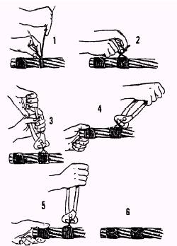
Figure 6-49.- Seizing wire rope. A rule of thumb for determining the size, number, and distance between seizing is as follows: The number of seizing to be applied equals approximately three times the diameter of the rope. Example: 3 x 3/ 4-inch-diameter rope = 2 1/ 4 inches. Round up to the next higher whole number and use three seizing. The width of each seizing should be 1 to 1 1/ 2 times as long as the diameter of the rope. Example: 1 x 3/ 4-inch-diameter rope = 3/ 4 inch. Use a 1-inch width of seizing. The seizing should be spaced a distance equal to twice the diameter of the wire rope. Example: 2 x 3/ 4-inch-diameter rope = 1 1/ 2 inches. Space the seizing 2 inches apart. A common method used to make a temporary wire rope seizing is as follows (fig. 6-49): Wind the seizing wire uniformly, using tension on the wire. After making the required number of turns, as shown in step 1, twist the ends of the wires counterclockwise by hand, so the twisted portion of the wires is near the middle of the seizing, as shown in step 2. Grasp the ends with end-cutting nippers and twist up slack, as shown in step 3. Do not try to tighten the seizing by twisting. Draw up on the seizing, as shown in step 4. Again twist up the slack, using the nippers as shown in step 5. Repeat steps 4 and 5 as needed. Cut the ends and pound them down on the rope, as shown in step 6. If the seizing is to be permanent, use a serving bar, or iron, to increase tension on the seizing wire when putting on the turns. Wire rope can be cut successfully by a number of methods. An effective and simple method is to use a hydraulic type of wire rope cutter, as shown in figure 6-50. Remember that all wire should be seized before it is cut. For best results in using this method, place the rope in the cutter so the blade comes between the two central seizing. With the release valve closed, jack the blade against the rope at the location of the cut and continue to operate the cutter until the wire rope is cut. When a hydraulic type of wire cutter is NOT available, other methods can be used. such as a hammer-type wire rope cutter (fig. 6-51), a cutting torch, and, if need be, a hacksaw and cold chisel. |
 |
|
|


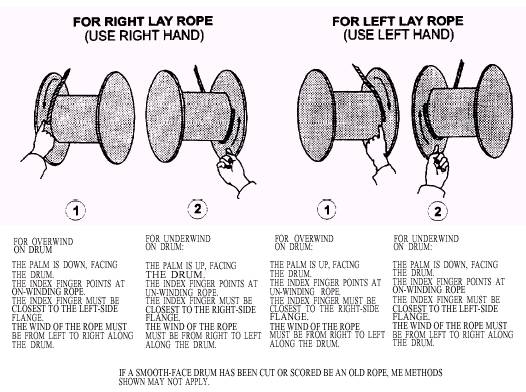 Figure 6-46.- Different