Custom Search
|
|
  |
|
|
The cross and roller design is the most common type of drive shaft U-joint. It consists of four bearing caps, four needle roller bearings, a cross or journal, grease seals, and snap rings (fig. 5-5). The bearing caps are held stationary in the drive shaft yokes. Roller bearings fit between the caps and the cross to reduce friction. The cross is free to rotate inside the caps and yokes. Snap rings usually fit into grooves cut in the caps or the yoke bores to secure the bearing caps and bearings. There are several other methods of securing the bearing caps in the yokes. These are bearing covers, U-bolts, and bearing caps.
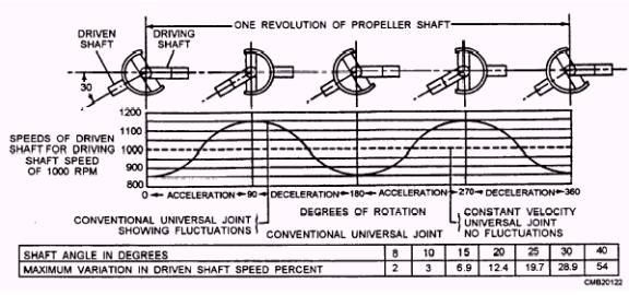
Figure 5-4.- Speed fluctuations caused by conventional universal joints.
Ball and Trunnion Universal Joint Variations in length is permitted by the longitudinal movement of the balls in the body grooves. Angular displacement is allowed by outward movement of the balls on the trunnion pins. This type of universal joint is recognized easily by the flexible dust boot that covers it. Double-Cardan Universal Joint As the shafts rotate, the action of the centering ball and yoke acts to maintain an equally divided drive angle between the connected shafts, resulting in a constant drive velocity. |
|
|
|