Share on Google+Share on FacebookShare on LinkedInShare on TwitterShare on DiggShare on Stumble Upon
Custom Search


HYDRAULIC SYSTEM
The hydraulic system of an automatic transmission serves four basic purposes:

1. Actuates clutches and brake bands by hydraulic pressure from the hydraulic slave circuits.

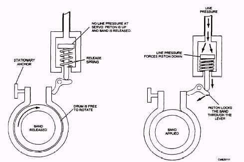
Figure 4-34.- Brake band operation.


Figure 4-35.- Operation of the accumulator.

2. Controls the shifting pattern of the transmission. This is done by switching hydraulic pressure to programmed combinations of clutches and brake bands based on vehicle speed and engine load.

3. Circulates the transmission fluid through a remote cooler to remove excess heat that is generated in the transmission and torque converter.

4. Provides a constant fresh supply of oil to all critical wearing surfaces of the transmission.

The hydraulic system for an automatic trans-mission typically consists of the following.

Pump
The typical hydraulic pump (fig. 4-36) is an internal-external rotor or gear-type pump. Located in the front of the transmission case, it is keyed to the torque converter hub so that it is driven by the engine. As the torque converter spins the oil pump, transmission fluid is drawn into the pump from the transmission pan. The pump compresses the oil and forces it to the pressure regulator. The pump has several basic functions:

Produces pressure to operate the clutches, the bands, and the gearsets.

Lubricates the moving parts in the transmission.

Keeps the torque converter filled with trans-mission fluid for proper operation.

Circulates transmission fluid through the trans-mission and cooling tank (radiator) to transfer heat.

Operates hydraulic valves in the transmission.


Western Governors University


Privacy Statement - Copyright Information. - Contact Us

Integrated Publishing, Inc. - A (SDVOSB) Service Disabled Veteran Owned Small Business