Custom Search
|
|
  |
|
|
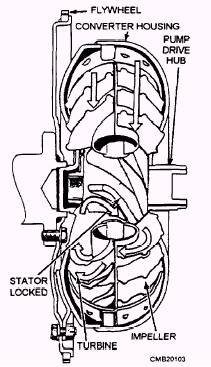
The torque converter is a fluid clutch that performs the same basic function as a manual transmission dry friction clutch (fig. 4-24). It provides a means of uncoupling the engine for stopping the vehicle in gear. It also provides a means of coupling the engine for acceleration. A torque converter has four basic parts: 1. Outer housing- normally made of two pieces of steel welded together in a doughnut shape, housing the impeller, stator, and turbine. The housing is filled with transmission fluid.
Figure 4-24.- Torque converter, partial cutaway view. 4. Stator- designed to improve oil circulation inside the torque converter. Increases efficiency and torque by causing the oil to swirl around the inside of the housing. The primary action of the torque converter results from the action of the impeller passing oil at an angle into the blades of the turbine. The oil pushes against the faces of the turbine vanes, causing the turbine to rotate in the same direction as the impeller (fig. 4-25). With the engine idling, the impeller spins slowly. Only a small amount of oil is thrown into the stator and turbine. Not enough force is developed inside the torque converter to spin the turbine. The vehicle remains stationary with the transmission in gear. During acceleration, the engine crankshaft, the converter housing, and the impeller begin to move faster. More oil is thrown out by centrifugal force, turning the turbine. As a result, the transmission input shaft and vehicle starts to move, but with some slippage.
Figure 4-25.- Torque converter in fluid coupling stage. At cruising speeds, the impeller and turbine spin at almost the same speed with very little slippage. When the impeller is spun fast enough, centrifugal force throws oil out hard enough to almost lock the impeller and turbine. After the oil has imparted its force to the turbine, the oil follows the contour of the turbine shell and blades so that it leaves the center section of the turbine spinning counterclockwise. Because the turbine has absorbed the force required to reverse the direction of the clockwise spinning of the oil, it now has greater force than is being delivered by the engine. The process of multiplying engine torque has begun. Torque multiplication refers to the ability of a torque converter to increase the amount of engine torque applied to the transmission input shaft. Torque multiplication occurs when the impeller is spinning faster than the turbine (fig. 4-26). For example, if the engine is accelerated quickly, the engine and impeller rpm might increase rapidly while the turbine is almost stationary. This is known as stall speed. Stall speed of a torque converter occurs when the impeller is at maximum speed without rotation of the turbine. This condition causes the transmission fluid to be thrown off the stator vanes at tremendous speeds. The greatest torque multiplication occurs at stall speed.
Figure 4-26.- Torque converter in torque multiplication
When the turbine speed nears impeller speed, torque multiplication drops off. Torque is increased in the converter by sacrificing motion. The turbine spins slower than the impeller during torque multiplication. If the counterclockwise oil were allowed to continue to the center section of the impeller, the oil would strike the blades of the pump in a direction that would hinder its rotation and cancel any gains in torque. To prevent this, you can add a stator assembly. The stator (fig. 4-27) is located between the pump and the turbine and is mounted on a one-way clutch that allows it to rotate clockwise but not counter-clockwise. The purpose of the stator is to redirect the oil returning from the turbine and change its rotation back to that of the impeller. Stator action is only needed when the impeller and turbine are turning at different speeds. The one-way clutch locks the stator when the impeller is turning faster than the turbine. This causes the stator to route oil flow over the impeller vanes properly. Then, when turbine speed almost equals impeller speed, the stator can freewheel on its shaft so not to obstruct flow. Even at normal highway speeds, there is a certain amount of slippage in the torque converter. Another type of torque converter that is common on modern vehicles is the lockup torque converter (fig. 4-28). The lockup torque converter provides increased fuel economy and increased transmission life through the elimination of heat caused by torque converter slippage. A typical lockup mechanism consists of a hydraulic piston, torsion springs, and clutch friction material. In lower gears, the converter clutch is released. The torque converter operates normally, allowing slippage and torque multiplication. However, when shifted into high or direct drive, transmission fluid is channeled to the converter piston. The converter piston pushes the friction discs together, locking the turbine and impeller. The crankshaft is able to drive the transmission input shaft directly, without slippage. The torsion springs assist to dampen engine power pulses entering the drive train.
Figure 4-28.- Torque converter with lockup clutch.
|
 |
|
|